
A105 Raised Face Blind Flange
A105 Raised Face Blind Flange
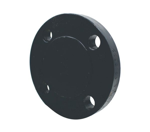
Item #: A105 Raised Face Blind Flange
Manufacturers:
The A105 Raised Face Blind Flange is a vital component in piping systems, designed to seal off the end of a pipeline or vessel, preventing the flow of fluids while providing easy access for inspection and maintenance. Manufactured in accordance with ASME B16.5 specifications, this blind flange is crafted from carbon steel, ensuring corrosion resistance and the ability to withstand high pressures and temperatures. The raised face design enhances the sealing capability by increasing the contact area with the gasket, ensuring a secure seal.
Products
Mechanical Properties
| Per ASTM A105-A105M - 24 | |||||
| Grade A105 | Tensile Strength | Yield Strength | Elongation in 4D | Reduction in Area | Hardness |
| Min ksi [MPa] | Min ksi [Mpa] | Min % | Min % | Max | |
| 70 [485] | 36 [250] | 22 | 30 | 197 |
Dimensional Specifications


Class #150 Dimensions |
Drilling | Length of Bolts | |||||||
| Pipe Size | Outside Diameter of Flange | Thickness of Flange (Min.) | Diameter of Bolt Circle | Diameter of Bolt Holes | Number of Bolt Holes | Diameter of Bolts | Stud Bolts Raised Face 0.06 in. | Stud Bolts Ring Joint | Machine Bolts Raised Face 0.06 in. |
| O.D. | C | M | P | P | P | ||||
| 1/2 | 3.50 | 0.38 | 2.38 | 5/8 | 4 | 1/2 | 2.25 | 2.00 | |
| 3/4 | 3.88 | 0.44 | 2.75 | 5/8 | 4 | 1/2 | 2.50 | 2.00 | |
| 1 | 4.25 | 0.50 | 3.12 | 5/8 | 4 | 1/2 | 2.50 | 3.00 | 2.25 |
| 1 1/4 | 4.62 | 0.56 | 3.50 | 5/8 | 4 | 1/2 | 2.75 | 3.25 | 2.25 |
| 1 1/2 | 5.00 | 0.62 | 3.88 | 5/8 | 4 | 1/2 | 2.75 | 3.25 | 2.50 |
| 2 | 6.00 | 0.69 | 4.75 | 3/4 | 4 | 5/8 | 3.25 | 3.75 | 2.75 |
| 2 1/2 | 7.00 | 0.81 | 5.50 | 3/4 | 4 | 5/8 | 3.50 | 4.00 | 3.00 |
| 3 | 7.50 | 0.88 | 6.00 | 3/4 | 4 | 5/8 | 3.50 | 4.00 | 3.00 |
| 3 1/2 | 8.50 | 0.88 | 7.00 | 3/4 | 8 | 5/8 | 3.50 | 4.00 | 3.00 |
| 4 | 9.00 | 0.88 | 7.50 | 3/4 | 8 | 5/8 | 3.50 | 4.00 | 3.00 |
| 5 | 10.00 | 0.88 | 8.50 | 7/8 | 8 | 3/4 | 3.75 | 4.25 | 3.25 |
| 6 | 11.00 | 0.94 | 9.50 | 7/8 | 8 | 3/4 | 4.00 | 4.50 | 3.25 |
| 8 | 13.50 | 1.06 | 11.75 | 7/8 | 8 | 3/4 | 4.25 | 4.75 | 3.50 |
| 10 | 16.00 | 1.12 | 14.25 | 1 | 12 | 7/8 | 4.50 | 5.00 | 4.00 |
| 12 | 19.00 | 1.19 | 17.00 | 1 | 12 | 7/8 | 4.75 | 5.25 | 4.00 |
| 14 | 21.00 | 1.31 | 18.75 | 1 1/8 | 12 | 1 | 5.25 | 5.75 | 4.50 |
| 16 | 23.50 | 1.38 | 21.25 | 1 1/8 | 16 | 1 | 5.25 | 5.75 | 4.50 |
| 18 | 25.00 | 1.50 | 22.75 | 1 1/4 | 16 | 1 1/8 | 5.75 | 6.25 | 5.00 |
| 20 | 27.50 | 1.62 | 25.00 | 1 1/4 | 20 | 1 1/8 | 6.25 | 6.75 | 5.50 |
| 24 | 32.00 | 1.81 | 29.50 | 1 3/8 | 20 | 1 1/8 | 6.75 | 7.25 | 6.00 |
Class #300 Dimensions |
Drilling | Length of Bolts | |||||||
| Pipe Size | Outside Diameter of Flange | Thickness of Flange (Min.) | Diameter of Bolt Circle | Diameter of Bolt Holes | Number of Bolt Holes | Diameter of Bolts | Stud Bolts Raised Face 0.06 in. | Stud Bolts Ring Joint | Machine Bolts Raised Face 0.06 in. |
| O.D. | C | M | P | P | P | ||||
| 1/2 | 3.75 | 0.5 | 2.62 | 5/8 | 4 | 1/2 | 2.50 | 3.00 | 2.25 |
| 3/4 | 4.62 | 0.56 | 3.25 | 3/4 | 4 | 5/8 | 3.00 | 3.50 | 2.50 |
| 1 | 4.88 | 0.62 | 3.5 | 3/4 | 4 | 5/8 | 3.00 | 3.50 | 2.50 |
| 1 1/4 | 5.25 | 0.69 | 3.88 | 3/4 | 4 | 5/8 | 3.25 | 3.75 | 2.75 |
| 1 1/2 | 6.12 | 0.75 | 4.50 | 7/8 | 4 | 3/4 | 3.50 | 4.00 | 3.00 |
| 2 | 6.50 | 0.81 | 5.00 | 3/4 | 8 | 5/8 | 3.50 | 4.00 | 3.00 |
| 2 1/2 | 7.50 | 0.94 | 5.88 | 7/8 | 8 | 3/4 | 4.00 | 4.50 | 3.25 |
| 3 | 8.25 | 1.06 | 6.62 | 7/8 | 8 | 3/4 | 4.25 | 4.75 | 3.50 |
| 3 1/2 | 9.00 | 1.12 | 7.25 | 7/8 | 8 | 3/4 | 4.25 | 5.00 | 3.75 |
| 4 | 10.00 | 1.19 | 7.88 | 7/8 | 8 | 3/4 | 4.50 | 5.00 | 3.75 |
| 5 | 11.00 | 1.31 | 9.25 | 7/8 | 8 | 3/4 | 4.75 | 5.25 | 4.25 |
| 6 | 12.50 | 1.38 | 10.62 | 7/8 | 12 | 3/4 | 4.75 | 5.50 | 4.25 |
| 8 | 15.00 | 1.56 | 13.00 | 1 | 12 | 7/8 | 5.50 | 6.00 | 4.75 |
| 10 | 17.50 | 1.81 | 15.25 | 1 1/8 | 16 | 1 | 6.25 | 6.75 | 5.50 |
| 12 | 20.50 | 1.94 | 17.75 | 1 1/4 | 16 | 1 1/8 | 6.75 | 7.25 | 5.75 |
| 14 | 23.00 | 2.06 | 20.25 | 1 1/4 | 20 | 1 1/8 | 7.00 | 7.50 | 6.25 |
| 16 | 25.50 | 2.19 | 22.50 | 1 3/8 | 20 | 1 1/4 | 7.50 | 8.00 | 6.50 |
| 18 | 28.00 | 2.31 | 24.75 | 1 3/8 | 24 | 1 1/4 | 7.75 | 8.25 | 6.75 |
| 20 | 30.50 | 2.44 | 27.00 | 1 3/8 | 24 | 1 1/4 | 8.00 | 8.75 | 7.25 |
| 24 | 36.00 | 2.69 | 32.00 | 1 5/8 | 24 | 1 1/2 | 9.00 | 10.00 | 8.00 |
Class #600 Dimensions |
Drilling | Length of Bolts | |||||||
| Pipe Size | Outside Diameter of Flange | Thickness of Flange (Min.) | Diameter of Bolt Circle | Diameter of Bolt Holes | Number of Bolt Holes | Diameter of Bolts | Raised Face 0.25 in. | Tongue & Groove | Ring Joint |
| O.D. | C | M | P | P | P | ||||
| 1/2 | 3.75 | 0.56 | 2.62 | 5/8 | 4 | 1/2 | 3.00 | 2.75 | 3.00 |
| 3/4 | 4.62 | 0.62 | 3.25 | 3/4 | 4 | 5/8 | 3.50 | 3.25 | 3.50 |
| 1 | 4.88 | 0.69 | 3.50 | 3/4 | 4 | 5/8 | 3.50 | 3.25 | 3.50 |
| 1 1/4 | 5.25 | 0.81 | 3.88 | 3/4 | 4 | 5/8 | 3.75 | 3.50 | 3.75 |
| 1 1/2 | 6.12 | 0.88 | 4.50 | 7/8 | 4 | 3/4 | 4.25 | 4.00 | 4.25 |
| 2 | 6.50 | 1.00 | 5.00 | 3/4 | 8 | 5/8 | 4.25 | 4.00 | 4.25 |
| 2 1/2 | 7.50 | 1.12 | 5.88 | 7/8 | 8 | 3/4 | 4.75 | 4.50 | 4.75 |
| 3 | 8.25 | 1.25 | 6.62 | 7/8 | 8 | 3/4 | 5.00 | 4.75 | 5.00 |
| 3 1/2 | 9.00 | 1.38 | 7.25 | 1 | 8 | 7/8 | 5.50 | 5.25 | 5.50 |
| 4 | 10.75 | 1.50 | 8.50 | 1 | 8 | 7/8 | 5.75 | 5.50 | 5.75 |
| 5 | 13.00 | 1.75 | 10.50 | 1 1/8 | 8 | 1 | 6.50 | 6.25 | 6.50 |
| 6 | 14.00 | 1.88 | 11.50 | 1 1/8 | 12 | 1 | 6.75 | 6.50 | 6.75 |
| 8 | 16.50 | 2.19 | 13.75 | 1 1/4 | 12 | 1 1/8 | 7.50 | 7.25 | 7.75 |
| 10 | 20.00 | 2.50 | 17.00 | 1 3/8 | 16 | 1 1/4 | 8.50 | 8.25 | 8.50 |
| 12 | 22.00 | 2.62 | 19.25 | 1 3/8 | 20 | 1 1/4 | 8.75 | 8.50 | 8.75 |
| 14 | 23.75 | 2.75 | 20.75 | 1 1/2 | 20 | 1 3/8 | 9.25 | 9.00 | 9.25 |
| 16 | 27.00 | 3.00 | 23.75 | 1 5/8 | 20 | 1 1/2 | 10.00 | 9.75 | 10.00 |
| 18 | 29.25 | 3.25 | 25.75 | 1 3/8 | 20 | 1 5/8 | 10.75 | 10.5 | 10.75 |
| 20 | 32.00 | 3.50 | 28.50 | 1 3/8 | 24 | 1 5/8 | 11.25 | 11.00 | 11.50 |
| 24 | 37.00 | 4.00 | 33.00 | 2 | 24 | 1 7/8 | 13.00 | 12.75 | 13.25 |
Class #900 Dimensions |
Drilling | Length of Bolts | |||||||||||||||||||||||||
| Pipe Size | Outside Diameter of Flange | Thickness of Flange (Min.) | Diameter of Bolt Circle | Diameter of Bolt Holes | Number of Bolt Holes | Diameter of Bolts | Raised Face 0.25 in. | Tongue & Groove | Ring Joint | ||||||||||||||||||
| O.D. | C | M | P | P | P | ||||||||||||||||||||||
| 1/2 | 4.75 | 0.88 | 3.25 | 7/8 | 4 | 3/4 | 4.25 | 4.00 | 4.25 | ||||||||||||||||||
| 3/4 | 5.12 | 1.00 | 3.50 | 7/8 | 4 | 3/4 | 4.50 | 4.25 | 4.50 | ||||||||||||||||||
| 1 | 5.88 | 1.12 | 4.00 | 1 | 4 | 7/8 | 5.00 | 4.75 | 5.00 | ||||||||||||||||||
| 1 1/4 | 6.25 | 1.12 | 4.38 | 1 | 4 | 7/8 | 5.00 | 4.75 | 5.00 | ||||||||||||||||||
| 1 1/2 | 7.00 | 1.25 | 4.88 | 1 1/8 | 4 | 1 | 5.50 | 5.25 | 5.50 | ||||||||||||||||||
| 2 | 8.50 | 1.50 | 6.50 | 1 | 8 | 7/8 | 5.75 | 5.50 | 5.75 | ||||||||||||||||||
| 2 1/2 | 9.62 | 1.62 | 7.50 | 1 1/8 | 8 | 1 | 6.25 | 6.00 | 6.25 | ||||||||||||||||||
| 3 | 9.50 | 1.50 | 7.50 | 1 | 8 | 7/8 | 5.75 | 5.50 | 5.75 | ||||||||||||||||||
| 4 | 11.50 | 1.75 | 9.25 | 1 1/4 | 8 | 1 1/8 | 6.75 | 6.50 | 6.75 | ||||||||||||||||||
| 5 | 13.75 | 2.00 | 11.00 | 1 3/8 | 8 | 1 1/4 | 7.50 | 7.25 | 7.50 | ||||||||||||||||||
| 6 |
Chemical Properties
Governing Standards
Loading product details...
| ||||||||||||||||||||||||||