
Fig G292 Beam Clamp With Eye Nut, Galvanized
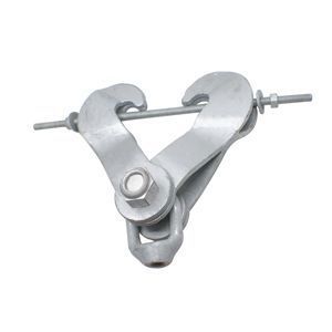
Fig G292 Beam Clamp With Eye Nut, Galvanized
Manufacturers:
The figure G292 hot dipped galvanized beam clamp w/weldless eye nut is used when welding to the structure is prohibited for supports and where some movement is expected. The clamping effect is produced by the “ice tong” action of the arms and is locked in place by the through bolt located just under the beam flange.
Products
Product Details
| MATERIAL | Hot Dipped Galvanized Carbon Steel with Forged Steel Eye Nut |
| COMPLIANCE | Federal Specification A-A-1192A (Type 4), ANSI/MSS SP-58 (Type 4) |
| NOTE | Fit jaws over edges of lower beam flanges and tighten nuts on tie rod to lock clamp in place. Weldless eye nut provides for horizontal pipe movement without binding, and is furnished tapped to any specific rod size up to the maximum rod size. Tie rod assures a tight non-slip fit to the beam. The application of a load to a structural beam by means of a beam clamp produces a transverse stress, perpendicular to the axis of the beam, in the flange to which the load is applied. |
Installation Drawings


Dimensions & Loads

| CLAMP SIZE |
MAX LOAD |
ROD SIZE A |
BEAM WIDTH |
BODY SIZE |
MAX FLANGE THICKNESS |
WEIGHT EACH |
| 1 | 610 | 3/8 | 3 - 8 | A | 0.6 | 5.5 |
| 1 | 1130 | 1/2 | 3 - 8 | A | 0.6 | 5.5 |
| 1 | 1810 | 5/8 | 3 - 8 | A | 0.6 | 5.5 |
| 1 | 2710 | 3/4 | 3 - 8 | A | 0.6 | 5.5 |
| 2 | 3700 | 7/8 | 3 - 8 | A | 0.6 | 5.5 |
| 2 | 4960 | 1 | 3 - 8 | A | 0.6 | 5.5 |
| 3 | 610 | 3/8 | 4 - 11 | B | 0.6 | 9.0 |
| 3 | 1130 | 1/2 | 4 - 11 | B | 0.6 | 9.0 |
| 3 | 1810 | 5/8 | 4 - 11 | B | 0.6 | 9.0 |
| 3 | 2710 | 3/4 | 4 - 11 | B | 0.6 | 9.0 |
| 3 | 3700 | 7/8 | 4 - 11 | B | 0.6 | 9.0 |
| 3 | 4960 | 1 | 4 - 11 | B | 0.6 | 9.0 |
| 4 | 610 | 3/8 | 4 - 12 | C | 1.03 | 29.0 |
| 4 | 1130 | 1/2 | 4 - 12 | C | 1.03 | 29.0 |
| 4 | 1810 | 5/8 | 4 - 12 | C | 1.03 | 29.0 |
| 4 | 2710 | 3/4 | 4 - 12 | C | 1.03 | 29.0 |
| 4 | 3700 | 7/8 | 4 - 12 | C | 1.03 | 29.0 |
| 4 | 4960 | 1 | 4 - 12 | C | 1.03 | 29.0 |
| 5 | 610 | 3/8 | 11 - 15 | D | 1.03 | 33.3 |
| 5 | 1130 | 1/2 | 11 - 15 | D | 1.03 | 33.3 |
| 5 | 1810 | 5/8 | 11 - 15 | D | 1.03 | 33.3 |
| 5 | 2710 | 3/4 | 11 - 15 | D | 1.03 | 33.3 |
| 5 | 3700 | 7/8 | 11 - 15 | D | 1.03 | 33.3 |
| 5 | 4960 | 1 | 11 - 15 | D | 1.03 | 33.3 |
| 6 | 8000 | 1 1/4 | 4 - 12 | C | 1.03 | 29.0 |
| 6 | 11500 | 1 1/2 | 4 - 12 | C | 1.03 | 29.0 |
| 7 | 8000 | 1 1/4 | 11 - 15 | D | 1.03 | 33.3 |
| 7 | 11500 | 1 1/2 | 11 - 15 | D | 1.03 | 33.3 |
| 8 | 11500 | 1 3/4 | 4 - 12 | C | 1.03 | 29.0 |
| 8 | 11500 | 2 | 4 - 12 | C | 1.03 | 29.0 |
| 8 | 11500 | 1 3/4 | 4 - 12 | C | 1.03 | 29.0 |
| 8 | 11500 | 2 | 4 - 12 | C | 1.03 | 29.0 |
- *Based on the allowable stresses shown in ANSI Code for Pressure Piping
| CLAMP SIZE | 1 | 2 | 3 | 4 | 5 | 6 | 7 | 8 | |
| BODY SIZE | A | A | B | C | D | C | D | C | |
| ROD TAKEOUT “E” FOR WIDTH OF BEAM |
3" | 5 3/16 | 5 3/16 | ||||||
| 4" | 5 1/8 | 5 1/8 | 8 1/4 | 8 5/8 | 8 5/8 | 11 5/8 | |||
| 5" | 5 | 5 | 8 1/8 | 8 5/8 | 8 5/8 | 11 1/2 | |||
| 6" | 4 13/16 | 4 13/16 | 8 1/8 | 8 1/2 | 8 1/2 | 11 1/2 | |||
| 7" | 4 3/8 | 4 3/8 | 7 7/8 | 8 3/8 | 8 3/8 | 11 3/8 | |||
| 8" | 3 15/16 | 3 15/16 | 7 3/4 | 8 1/8 | 8 1/8 | 11 1/8 | |||
| 9" | 7 3/8 | 7 3/8 | 7 7/8 | 10 7/8 | |||||
| 10" | 7 5/8 | 7 5/8 | 7 5/8 | 10 3/4 | |||||
| 11" | 7 | 7 | 9 1/2 | 7 | 9 3/4 | 10 1/2 | |||
| 12" | 6 3/4 | 6 3/4 | 9 1/4 | 6 3/4 | 9 1/2 | 10 | |||
| 13" | 8 7/8 | 9 1/8 | |||||||
| 14" | 8 3/8 | 8 3/4 | |||||||
| 15" | 7 7/8 | 8 1/8 | |||||||
- All dimensions are in inches.