
Serrated Flange Lock Nut, Plated
Serrated Flange Lock Nut, Plated
Manufacturers:
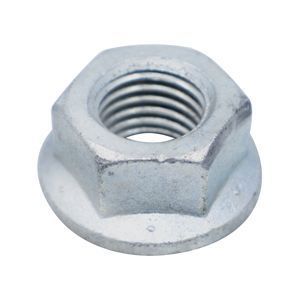
Case hardened serrated flange lock nuts eliminate the need for a lock washer or washer, as the flange serves to distribute the bearing load over a greater area. The bearing surface has circular serrations that fan out so that once the serrated flange makes contact with the mating surface, the serrations cut into and displace the mating material upon tightening. All metal lock nuts are resistant to high temperatures and high chemical exposures, as they are made from one material. Dimensional specifications are governed by ASME B18.16.4. Available in zinc plated finish. Zinc plating sacrifices itself, corroding before the base material, offering added corrosion resistance.
Products
Dimensional Specifications

| Per ASME B18.16.4-2008 | |||||||||||||
| Nominal Diameter | UNC | UNF | F | G | B | H | J | K | |||||
| Width Across Flats | Width Across Corners | Flange Diameter | Nut Thickness | Hex Height |
Flange Thickness |
||||||||
| Max | Min | Max | Min | Max | Min | Max | Min | ||||||
| #6 | 0.1380 | 32 | 40 | 0.3120 | 0.3020 | 0.3610 | 0.3420 | 0.4220 | 0.4060 | 0.1710 | 0.1560 | 0.1000 | 0.0200 |
| #8 | 0.1640 | 32 | 36 | 0.3440 | 0.3340 | 0.3970 | 0.3810 | 0.4690 | 0.4520 | 0.2030 | 0.1870 | 0.1300 | 0.0200 |
| #10 | 0.1900 | 24 | 32 | 0.3750 | 0.3650 | 0.4330 | 0.4160 | 0.5000 | 0.4800 | 0.2190 | 0.2030 | 0.1300 | 0.0300 |
| #12 | 0.2160 | 24 | 28 | 0.4380 | 0.4280 | 0.5050 | 0.4880 | 0.5940 | 0.5740 | 0.2360 | 0.2220 | 0.1400 | 0.0400 |
| 1/4 | 0.2500 | 20 | 28 | 0.4380 | 0.4280 | 0.5050 | 0.4880 | 0.5940 | 0.5740 | 0.2360 | 0.2222 | 0.1400 | 0.0400 |
| 5/16 | 0.3125 | 18 | 24 | 0.5000 | 0.4890 | 0.5770 | 0.5570 | 0.6800 | 0.6600 | 0.2830 | 0.2680 | 0.1700 | 0.0400 |
| 3/8 | 0.3750 | 16 | 24 | 0.5620 | 0.5510 | 0.6500 | 0.6280 | 0.7500 | 0.7280 | 0.3470 | 0.3300 | 0.2300 | 0.0400 |
| 7/16 | 0.4375 | 14 | 20 | 0.6880 | 0.6750 | 0.7940 | 0.7680 | 0.9370 | 0.9100 | 0.3950 | 0.3750 | 0.2600 | 0.0400 |
| 1/2 | 0.5000 | 13 | 20 | 0.7500 | 0.7360 | 0.8660 | 0.8400 | 1.0310 | 1.0000 | 0.4580 | 0.4370 | 0.3100 | 0.0500 |
| 9/16 | 0.5625 | 12 | 18 | 0.8750 | 0.8610 | 1.0100 | 0.9820 | 1.1880 | 1.1550 | 0.5060 | 0.4830 | 0.3500 | 0.0500 |
| 5/8 | 0.6250 | 11 | 18 | 0.9380 | 0.9220 | 1.0830 | 1.0510 | 1.2810 | 1.2480 | 0.5690 | 0.5450 | 0.4000 | 0.0500 |
| 3/4 | 0.7500 | 10 | 16 | 1.1250 | 1.0880 | 1.2990 | 1.2400 | 1.5000 | 1.4600 | 0.6750 | 0.6270 | 0.4600 | 0.0600 |
| 7/8 | 0.8750 | 9 | 14 | 1.1790 | 1.1660 | 1.3610 | 1.2950 | 1.6820 | * | 0.7860 | 0.7420 | * | 0.1100 |
- All dimensions are in inches.
Governing Standards
| ASME B18.16.4 | Covers the general, dimensional, and mechanical performance requirements for low strength carbon steel, case hardened, regular and large serrated flange locknuts (inch series), recognized as American National Standard. |
| ASME B1.1 UNC & UNF Class 2B | Specifies the thread form, series, class, allowance, tolerance, and designation for unified screw threads. |