
2H Heavy Hex Nut, Mechanical Galvanized
2H Heavy Hex Nut, Mechanical Galvanized
Manufacturers:
ASTM A194 Grade 2H heavy hex nuts are high-strength, heat-treated nuts designed for demanding applications, including flange bolting, structural connections, and use with high-strength bolts. These carbon and alloy steel nuts are ideal for high-pressure and high-temperature environments and are commonly paired with bolts like ASTM A193 Grade B7, F3125 Grade A325, and F1554 Grade 105. Featuring a larger bearing surface than standard hex nuts, they offer enhanced load distribution and durability. Each nut is marked with the "2H" grade symbol and the manufacturer's ID for traceability. Finished with a mechanically galvanized coating, they offer reliable corrosion resistance and meet dimensional standards set by ASME B18.2.2.
Products
Governing Standards
| ASTM A194 | This specification covers a variety of carbon, alloy, and martensitic stainless steel nuts in the size range 1⁄4 through 4 in. and metric M6 through M100 nominal. It also covers austenitic stainless steel nuts in the size range 1⁄4 in. and M6 nominal and above. These nuts are intended for high-pressure or high temperature service, or both. Grade substitutions without the purchaser’s permission are not allowed. |
| ASME B18.2.2 | Covers the complete general and dimensional data for the various types of inch series square and hex nuts, including machine screw nuts and coupling nuts. |
| ASME B1.1 UNC & UNF Class 2B | Specifies the thread form, series, class, allowance, tolerance, and designation for unified screw threads. |

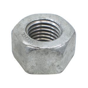
Grade 2H Material Marking
Chemical Properties
| Per ASTM A194/A194M-16 | ||||||
| Grade | Material | Carbon | Manganese | Phosphorus | Sulfur (1) | Silicon |
| % by weight | % by weight | % by weight | % by weight | % by weight | ||
| 2H | Carbon Steel | 0.40 min | 1.00 max | 0.040 max | 0.050 max | 0.04 max |
- 1. Because of the degree to which sulfur segregates, product analysis for sulfur over 0.060 % max is not technologically appropriate.
Dimensional Specifications

| Per ASME B18.2.2-2015 | ||||||||||||
| Nominal Diameter | UNC | UNF | UN8 | F | G | H | ||||||
| Width Across Flats | Width Across Corners | Thickness | ||||||||||
| Basic | Max | Min | Max | Min | Basic | Max | Min | |||||
| 1/4 | 0.250 | 20 | 28 | 1/2 | 0.500 | 0.488 | 0.577 | 0.556 | 15/64 | 0.250 | 0.218 | |
| 5/16 | 0.313 | 18 | 24 | 9/16 | 0.562 | 0.546 | 0.650 | 0.220 | 19/64 | 0.314 | 0.280 | |
| 3/8 | 0.375 | 16 | 24 | 11/16 | 0.688 | 0.669 | 0.794 | 0.763 | 23/64 | 0.377 | 0.341 | |
| 7/16 | 0.438 | 14 | 20 | 3/4 | 0.750 | 0.728 | 0.866 | 0.830 | 27/64 | 0.441 | 0.403 | |
| 1/2 | 0.500 | 13 | 20 | 7/8 | 0.875 | 0.850 | 1.010 | 0.990 | 31/64 | 0.504 | 0.464 | |
| 9/16 | 0.563 | 12 | 18 | 15/16 | 0.938 | 0.909 | 1.083 | 1.037 | 35/64 | 0.568 | 0.526 | |
| 5/8 | 0.625 | 11 | 18 | 1 1/16 | 1.062 | 1.031 | 1.227 | 1.175 | 39/64 | 0.631 | 0.587 | |
| 3/4 | 0.750 | 10 | 16 | 1 1/4 | 1.250 | 1.212 | 1.443 | 1.382 | 47/64 | 0.758 | 0.710 | |
| 7/8 | 0.875 | 9 | 14 | 1 7/16 | 1.438 | 1.394 | 1.660 | 1.589 | 55/64 | 0.885 | 0.833 | |
| 1 | 1.000 | 8 | 14 | 1 5/8 | 1.625 | 1.575 | 1.876 | 1.796 | 63/64 | 1.012 | 0.956 | |
| 1 1/8 | 1.125 | 7 | 12 | 8 | 1 13/16 | 1.812 | 1.756 | 2.093 | 2.002 | 1 7/64 | 1.139 | 1.079 |
| 1 1/4 | 1.250 | 7 | 12 | 8 | 2 | 2.000 | 1.380 | 2.309 | 2.209 | 1 7/32 | 1.251 | 1.187 |
| 1 3/8 | 1.375 | 6 | 12 | 8 | 2 3/16 | 2.188 | 2.119 | 2.526 | 2.416 | 1 11/32 | 1.378 | 1.310 |
| 1 1/2 | 1.500 | 6 | 12 | 8 | 2 3/8 | 2.375 | 2.300 | 2.742 | 2.622 | 1 15/32 | 1.505 | 1.433 |
| 1 5/8 | 1.625 | 5 1/2 | 12 | 8 | 2 9/16 | 2.562 | 2.481 | 2.959 | 2.828 | 1 19/32 | 1.632 | 1.556 |
| 1 3/4 | 1.750 | 5 | 12 | 8 | 2 3/4 | 2.750 | 2.662 | 3.175 | 3.035 | 1 23/32 | 1.759 | 1.679 |
| 1 7/8 | 1.875 | 5 | 12 | 8 | 2 15/16 | 2.938 | 2.844 | 3.392 | 3.242 | 1 27/32 | 1.886 | 1.802 |
| 2 | 2.000 | 4 1/2 | 12 | 8 | 3 1/8 | 3.125 | 3.025 | 3.608 | 3.449 | 1 31/32 | 2.013 | 1.925 |
| 2 1/4 | 2.250 | 4 1/2 | 12 | 8 | 3 1/2 | 3.500 | 3.388 | 4.041 | 3.862 | 2 13/64 | 2.251 | 2.155 |
| 2 1/2 | 2.500 | 4 | 12 | 8 | 3 7/8 | 3.875 | 3.750 | 4.474 | 4.275 | 2 29/64 | 2.505 | 2.401 |
| 2 3/4 | 2.750 | 4 | 12 | 8 | 4 1/4 | 4.250 | 4.112 | 4.907 | 4.688 | 2 45/64 | 2.759 | 2.647 |
| 3 | 3.000 | 4 | 12 | 8 | 4 5/8 | 4.625 | 4.475 | 5.340 | 5.102 | 2 61/64 | 3.013 | 2.893 |
| 3 1/4 | 3.250 | 4 | 12 | 8 | 5 | 5.000 | 4.838 | 5.774 | 5.515 | 3 3/16 | 3.252 | 3.124 |
| 3 1/2 | 3.500 | 4 | 12 | 8 | 5 3/8 | 5.375 | 5.200 | 6.207 | 5.928 | 3 7/16 | 3.506 | 3.370 |
| 3 3/4 | 3.750 | 4 | 12 | 8 | 5 3/4 | 5.750 | 5.562 | 5.562 | 6.341 | 3 11/16 | 3.670 | 3.616 |
| 4 | 4.000 | 4 | 12 | 8 | 6 1/8 | 6.125 | 5.925 | 5.925 | 6.755 | 3 15/16 | 4.014 | 3.862 |
- All dimensions are in inches.
Mechanical Properties
| Carbon Steel, Quenched & Tempered | Per ASTM A194/A194M-16 | |||
| Diameter | Proof Load Stress | Core Hardness | Tempering Temperature | |
| Min psi | Rockwell | Min | ||
| Min | Max | |||
| 1/4" thru 1 1/2" | 175,000 | C24 | C35 | 850F |
| Over 1 1/2" | 175,000 | C35 | 850F | |