
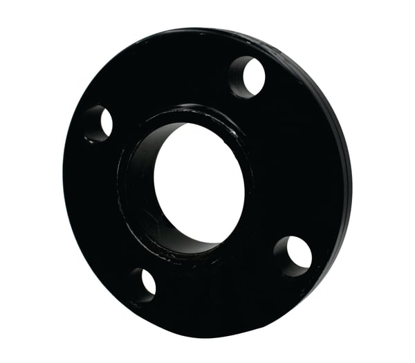
A105 Raised Face Slip-On Flange
A105 Raised Face Slip-On Flange
Item #: A105 Raised Face Slip-On Flange
Manufacturers:
The A105 Raised Face Slip-On Flange is an essential fitting in piping systems, designed for easy connection to pipes and equipment. Manufactured in accordance with ASME B16.5 specifications, this flange is made from carbon steel, whose raised face design enhances the sealing surface, allowing for a tight connection when paired with gaskets. Its slip-on configuration facilitates straightforward installation, as it can be easily aligned and welded to the pipe.
Products
Mechanical Properties
| Per ASTM A105-A105M - 24 | |||||
| Grade A105 | Tensile Strength | Yield Strength | Elongation in 4D | Reduction in Area | Hardness |
| Min ksi [MPa] | Min ksi [Mpa] | Min % | Min % | Max | |
| 70 [485] | 36 [250] | 22 | 30 | 197 |
Chemical Properties
| Element | Carbon | Manganese | Phosphorus | Sulfur | Silicon | Copper | Nickel | Chromium | Molybdenum | Vanadium |
| Composition, % | 0.35 max | 0.60-1.05 | 0.035 max | 0.040 max | 0.10-0.35 | 0.40 max (1) | 0.40 max (1) | 0.30 max (1-2) | 0.12 max (1-2) | 0.08 max |
- 1. The sum of copper, nickel, chromium, molybdenum and vanadium shall not exceed 1.00%
- 2. The sum of chromium and molybdenum shall not exceed 0.32%
- Note: For each reduction of 0.01% below the specified carbon maximum (0.35%), an increase of 0.006% manganese above the specified maximum (1.05%) will be permitted up to a maximum of 1.35%.
Governing Standards
| ASTM A105 | Covers forged carbon steel piping components for ambient- and higher-temperature service in pressure systems. Included are flanges, fittings, Valves, and similar parts ordered either to dimensions specified by the purchaser or to dimensional standards. |
|---|---|
| ASME B16.11 | Covers ratings, dimensions, tolerances, marking and material requirements for socket-welding and threaded forged fittings. These fittings are designated as Class 2000, 3000, and 6000 for threaded end fittings and Class 3000, 6000, and 9000 for socket-weld end fittings. |
Dimensional Specifications


Class #150 Dimensions |
Length Through Hub | Bore | Drilling | Length of Bolts | |||||||||
| Pipe Size | Outside Diameter of Flange | Thickness of Flange (Min.) | Diameter of Hub | Threaded Length Through Hub Neck | Thread Length (Min.) | Slip-on Bore (Min.) | Diameter of Bolt Circle | Diameter of Bolt Holes | Number of Bolt Holes | Diameter of Bolts | Stud Bolts Raised Face 0.06 in. | Stud Bolts Ring Joint | Machine Bolts Raised Face 0.06 in. |
| O.D. | C | W | Y2 | T | B2 | M | P | P | P | ||||
| 1/2 | 3.50 | 0.38 | 1.19 | 0.56 | 0.62 | 0.88 | 2.38 | 5/8 | 4.00 | 1/2 | 2.25 | 2.00 | |
| 3/4 | 3.88 | 0.44 | 1.50 | 0.56 | 0.62 | 1.09 | 2.75 | 5/8 | 4.00 | 1/2 | 2.50 | 2.00 | |
| 1 | 4.25 | 0.50 | 1.94 | 0.62 | 0.69 | 1.36 | 3.12 | 5/8 | 4.00 | 1/2 | 2.50 | 3.00 | 2.25 |
| 1 1/4 | 4.62 | 0.56 | 2.31 | 0.75 | 0.81 | 1.7 | 3.50 | 5/8 | 4.00 | 1/2 | 2.75 | 3.25 | 2.25 |
| 1 1/2 | 5.00 | 0.62 | 2.56 | 0.81 | 0.88 | 1.95 | 3.88 | 5/8 | 4.00 | 1/2 | 2.75 | 3.25 | 2.50 |
| 2 | 6.00 | 0.69 | 3.06 | 0.94 | 1.00 | 2.44 | 4.75 | 3/4 | 4.00 | 5/8 | 3.25 | 3.75 | 2.75 |
| 2 1/2 | 7.00 | 0.81 | 3.56 | 1.06 | 1.12 | 2.94 | 5.50 | 3/4 | 4.00 | 5/8 | 3.50 | 4.00 | 3.00 |
| 3 | 7.50 | 0.88 | 4.25 | 1.12 | 1.19 | 3.57 | 6.00 | 3/4 | 4.00 | 5/8 | 3.50 | 4.00 | 3.00 |
| 3 1/2 | 8.50 | 0.88 | 4.81 | 1.19 | 1.25 | 4.07 | 7.00 | 3/4 | 8.00 | 5/8 | 3.50 | 4.00 | 3.00 |
| 4 | 9.00 | 0.88 | 5.31 | 1.25 | 1.31 | 4.57 | 7.50 | 3/4 | 8.00 | 5/8 | 3.50 | 4.00 | 3.00 |
| 5 | 10.00 | 0.88 | 6.44 | 1.38 | 1.44 | 5.66 | 8.50 | 7/8 | 8.00 | 3/4 | 3.75 | 4.25 | 3.25 |
| 6 | 11.00 | 0.94 | 7.56 | 1.50 | 1.56 | 6.72 | 9.50 | 7/8 | 8.00 | 3/4 | 4.00 | 4.50 | 3.25 |
| 8 | 13.50 | 1.06 | 9.69 | 1.69 | 1.75 | 8.72 | 11.75 | 7/8 | 8.00 | 3/4 | 4.25 | 4.75 | 3.50 |
| 10 | 16.00 | 1.12 | 12.00 | 1.88 | 1.94 | 10.88 | 14.25 | 1 | 12.00 | 7/8 | 4.50 | 5.00 | 4.00 |
| 12 | 19.00 | 1.19 | 14.38 | 2.12 | 2.19 | 12.88 | 17.00 | 1 | 12.00 | 7/8 | 4.75 | 5.25 | 4.00 |
| 14 | 21.00 | 1.31 | 15.75 | 2.19 | 2.25 | 14.14 | 18.75 | 1 1/8 | 12.00 | 1 | 5.25 | 5.75 | 4.50 |
| 16 | 23.50 | 1.38 | 18.00 | 2.44 | 2.50 | 16.16 | 21.25 | 1 1/8 | 16.00 | 1 | 5.25 | 5.75 | 4.50 |
| 18 | 25.00 | 1.50 | 19.80 | 2.62 | 2.69 | 18.18 | 22.75 | 1 1/4 | 16.00 | 1 1/8 | 5.75 | 6.25 | 5.00 |
| 20 | 27.50 | 1.62 | 22.00 | 2.81 | 2.88 | 20.2 | 25.00 | 1 1/4 | 20.00 | 1 1/8 | 6.25 | 6.75 | 5.50 |
| 24 | 32.00 | 1.81 | 26.12 | 3.19 | 3.25 | 24.25 | 29.50 | 1 3/8 | 20.00 | 1 1/8 | 6.75 | 7.25 | 6.00 |
Class #300 Dimensions |
Drilling | Length of Bolts | Length Through Hub | Bore | ||||||||
| Pipe Size | Outside Diameter of Flange | Thickness of Flange (Min.) | Diameter of Bolt Circle | Diameter of Bolt Holes | Number of Bolt Holes | Diameter of Bolts | Stud Bolts Raised Face 0.06 in. | Stud Bolts Ring Joint | Machine Bolts Raised Face 0.06 in. | Diameter of Hub | Threaded Length Through Hub Neck | Slip-on Bore (Min.) |
| O.D. | C | M | P | P | P | W | Y2 | B2 | ||||
| 1/2 | 3.75 | 0.5 | 2.62 | 5/8 | 4 | 1/2 | 2.50 | 3.00 | 2.25 | 1.50 | 0.81 | 0.88 |
| 3/4 | 4.62 | 0.56 | 3.25 | 3/4 | 4 | 5/8 | 3.00 | 3.50 | 2.50 | 1.88 | 0.94 | 1.09 |
| 1 | 4.88 | 0.62 | 3.5 | 3/4 | 4 | 5/8 | 3.00 | 3.50 | 2.50 | 2.12 | 1.00 | 1.36 |
| 1 1/4 | 5.25 | 0.69 | 3.88 | 3/4 | 4 | 5/8 | 3.25 | 3.75 | 2.75 | 2.50 | 1.00 | 1.70 |
| 1 1/2 | 6.12 | 0.75 | 4.50 | 7/8 | 4 | 3/4 | 3.50 | 4.00 | 3.00 | 2.75 | 1.13 | 1.95 |
| 2 | 6.50 | 0.81 | 5.00 | 3/4 | 8 | 5/8 | 3.50 | 4.00 | 3.00 | 3.31 | 1.25 | 2.44 |
| 2 1/2 | 7.50 | 0.94 | 5.88 | 7/8 | 8 | 3/4 | 4.00 | 4.50 | 3.25 | 3.94 | 1.44 | 2.94 |
| 3 | 8.25 | 1.06 | 6.62 | 7/8 | 8 | 3/4 | 4.25 | 4.75 | 3.50 | 4.62 | 1.63 | 3.57 |
| 3 1/2 | 9.00 | 1.12 | 7.25 | 7/8 | 8 | 3/4 | 4.25 | 5.00 | 3.75 | 5.25 | 1.69 | 4.07 |
| 4 | 10.00 | 1.19 | 7.88 | 7/8 | 8 | 3/4 | 4.50 | 5.00 | 3.75 | 5.75 | 1.82 | 4.57 |
| 5 | 11.00 | 1.31 | 9.25 | 7/8 | 8 | 3/4 | 4.75 | 5.25 | 4.25 | 7.00 | 1.94 | 5.66 |
| 6 | 12.50 | 1.38 | 10.62 | 7/8 | 12 | 3/4 | 4.75 | 5.50 | 4.25 | 8.12 | 2.00 | 6.72 |
| 8 | 15.00 | 1.56 | 13.00 | 1 | 12 | 7/8 | 5.50 | 6.00 | 4.75 | 10.25 | 2.38 | 8.72 |
| 10 | 17.50 | 1.81 | 15.25 | 1 1/8 | 16 | 1 | 6.25 | 6.75 | 5.50 | 12.62 | 2.56 | 10.88 |
| 12 | 20.50 | 1.94 | 17.75 | 1 1/4 | 16 | 1 1/8 | 6.75 | 7.25 | 5.75 | 14.75 | 2.82 | 12.88 |
| 14 | 23.00 | 2.06 | 20.25 | 1 1/4 | 20 | 1 1/8 | 7.00 | 7.50 | 6.25 | 16.75 | 2.94 | 14.14 |
| 16 | 25.50 | 2.19 | 22.50 | 1 3/8 | 20 | 1 1/4 | 7.50 | 8.00 | 6.50 | 19.00 | 3.19 | 16.16 |
| 18 | 28.00 | 2.31 | 24.75 | 1 3/8 | 24 | 1 1/4 | 7.75 | 8.25 | 6.75 | 21.00 | 3.44 | 18.18 |
| 20 | 30.50 | 2.44 | 27.00 | 1 3/8 | 24 | 1 1/4 | 8.00 | 8.75 | 7.25 | 23.12 | 3.69 | 20.20 |
| 24 | 36.00 | 2.69 | 32.00 | 1 5/8 | 24 | 1 1/2 | 9.00 | 10.00 | 8.00 | 27.62 | 4.13 | 24.25 |
Class #600 Dimensions |
Drilling | Length of Bolts | Length Through Hub | Bore | ||||||||
| Pipe Size | Outside Diameter of Flange | Thickness of Flange (Min.) | Diameter of Bolt Circle | Diameter of Bolt Holes | Number of Bolt Holes | Diameter of Bolts | Raised Face 0.25 in. | Tongue & Groove | Ring Joint | Diameter of Hub | Threaded Length Through Hub Neck | Slip-on Bore (Min.) |
| O.D. | C | M | P | P | P | W | Y2 | B2 | ||||
| 1/2 | 3.75 | 0.56 | 2.62 | 5/8 | 4 | 1/2 | 3.00 | 2.75 | 3.00 | 1.50 | 0.88 | 0.88 |
| 3/4 | 4.62 | 0.62 | 3.25 | 3/4 | 4 | 5/8 | 3.50 | 3.25 | 3.50 | 1.88 | 1 | 1.09 |
| 1 | 4.88 | 0.69 | 3.50 | 3/4 | 4 | 5/8 | 3.50 | 3.25 | 3.50 | 2.12 | 1.06 | 1.36 |
| 1 1/4 | 5.25 | 0.81 | 3.88 | 3/4 | 4 | 5/8 | 3.75 | 3.50 | 3.75 | 2.50 | 1.12 | 1.70 |
| 1 1/2 | 6.12 | 0.88 | 4.50 | 7/8 | 4 | 3/4 | 4.25 | 4.00 | 4.25 | 2.75 | 1.25 | 1.95 |
| 2 | 6.50 | 1.00 | 5.00 | 3/4 | 8 | 5/8 | 4.25 | 4.00 | 4.25 | 3.31 | 1.44 | 2.44 |
| 2 1/2 | 7.50 | 1.12 | 5.88 | 7/8 | 8 | 3/4 | 4.75 | 4.50 | 4.75 | 3.94 | 1.62 | 2.94 |
| 3 | 8.25 | 1.25 | 6.62 | 7/8 | 8 | 3/4 | 5.00 | 4.75 | 5.00 | 4.62 | 1.81 | 3.57 |
| 3 1/2 | 9.00 | 1.38 | 7.25 | 1 | 8 | 7/8 | 5.50 | 5.25 | 5.50 | 5.25 | 1.94 | 4.07 |
| 4 | 10.75 | 1.50 | 8.50 | 1 | 8 | 7/8 | 5.75 | 5.50 | 5.75 | 6.00 | 2.12 | 4.57 |
| 5 | 13.00 | 1.75 | 10.50 | 1 1/8 | 8 | 1 | 6.50 | 6.25 | 6.50 | 7.44 | 2.38 | 5.66 |
| 6 | 14.00 | 1.88 | 11.50 | 1 1/8 | 12 | 1 | 6.75 | 6.50 | 6.75 | 8.75 | 2.62 | 6.72 |
| 8 | 16.50 | 2.19 | 13.75 | 1 1/4 | 12 | 1 1/8 | 7.50 | 7.25 | 7.75 | 10.75 | 3 | 8.72 |
| 10 | 20.00 | 2.50 | 17.00 | 1 3/8 | 16 | 1 1/4 | ||||||