
A105 Raised Face Weld Neck Flange
A105 Raised Face Weld Neck Flange
Item #: A105 Raised Face Weld Neck Flange
Manufacturers:
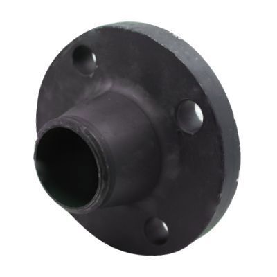
The A105 Raised Face Weld Neck Flange is an important component in piping systems, designed to provide a strong connection between pipes and equipment. Manufactured in accordance with ASME B16.5 specifications, this flange is constructed from carbon steel, ensuring its strength. The raised face design enhances the sealing surface, promoting a secure connection when used with gaskets.
Products
Dimensional Specifications


Class #150 Dimensions |
Bore | Drilling | Length of Bolts | |||||||||||
| Pipe Size | Outside Diameter of Flange | Thickness of Flange (Min.) | Diameter of Hub | Diameter of Weld Neck | Weld Neck Length Through Hub | Weld Neck & Socket Weld Neck Bore | Diameter of Bolt Circle | Diameter of Bolt Holes | Number of Bolt Holes | Diameter of Bolts | Stud Bolts Raised Face 0.06 in. | Stud Bolts Ring Joint | Machine Bolts Raised Face 0.06 in. | |
| O.D. | C | W | K | Y1 | B1 | M | P | P | P | |||||
| 1/2 | 3.50 | 0.38 | 1.19 | 0.84 | 1.81 | 0.62 | 2.38 | 5/8 | 4.00 | 1/2 | 2.25 | 2.00 | ||
| 3/4 | 3.88 | 0.44 | 1.50 | 1.05 | 2.00 | 0.82 | 2.75 | 5/8 | 4.00 | 1/2 | 2.50 | 2.00 | ||
| 1 | 4.25 | 0.50 | 1.94 | 1.32 | 2.12 | 1.05 | 3.12 | 5/8 | 4.00 | 1/2 | 2.50 | 3.00 | 2.25 | |
| 1 1/4 | 4.62 | 0.56 | 2.31 | 1.66 | 2.19 | 1.38 | 3.50 | 5/8 | 4.00 | 1/2 | 2.75 | 3.25 | 2.25 | |
| 1 1/2 | 5.00 | 0.62 | 2.56 | 1.90 | 2.38 | 1.61 | 3.88 | 5/8 | 4.00 | 1/2 | 2.75 | 3.25 | 2.50 | |
| 2 | 6.00 | 0.69 | 3.06 | 2.38 | 2.44 | 2.07 | 4.75 | 3/4 | 4.00 | 5/8 | 3.25 | 3.75 | 2.75 | |
| 2 1/2 | 7.00 | 0.81 | 3.56 | 2.88 | 2.69 | 2.47 | 5.50 | 3/4 | 4.00 | 5/8 | 3.50 | 4.00 | 3.00 | |
| 3 | 7.50 | 0.88 | 4.25 | 3.50 | 2.69 | 3.07 | 6.00 | 3/4 | 4.00 | 5/8 | 3.50 | 4.00 | 3.00 | |
| 3 1/2 | 8.50 | 0.88 | 4.81 | 4.00 | 2.75 | 3.55 | 7.00 | 3/4 | 8.00 | 5/8 | 3.50 | 4.00 | 3.00 | |
| 4 | 9.00 | 0.88 | 5.31 | 4.50 | 2.94 | 4.03 | 7.50 | 3/4 | 8.00 | 5/8 | 3.50 | 4.00 | 3.00 | |
| 5 | 10.00 | 0.88 | 6.44 | 5.56 | 3.44 | 5.05 | 8.50 | 7/8 | 8.00 | 3/4 | 3.75 | 4.25 | 3.25 | |
| 6 | 11.00 | 0.94 | 7.56 | 6.63 | 3.44 | 6.07 | 9.50 | 7/8 | 8.00 | 3/4 | 4.00 | 4.50 | 3.25 | |
| 8 | 13.50 | 1.06 | 9.69 | 8.63 | 3.94 | 7.98 | 11.75 | 7/8 | 8.00 | 3/4 | 4.25 | 4.75 | 3.50 | |
| 10 | 16.00 | 1.12 | 12.00 | 10.75 | 3.94 | 10.02 | 14.25 | 1 | 12.00 | 7/8 | 4.50 | 5.00 | 4.00 | |
| 12 | 19.00 | 1.19 | 14.38 | 12.75 | 4.44 | 12.00 | 17.00 | 1 | 12.00 | 7/8 | 4.75 | 5.25 | 4.00 | |
| 14 | 21.00 | 1.31 | 15.75 | 14.00 | 4.94 | 13.25 | 18.75 | 1 1/8 | 12.00 | 1 | 5.25 | 5.75 | 4.50 | |
| 16 | 23.50 | 1.38 | 18.00 | 16.00 | 4.94 | 15.25 | 21.25 | 1 1/8 | 16.00 | 1 | 5.25 | 5.75 | 4.50 | |
| 18 | 25.00 | 1.50 | 19.80 | 18.00 | 5.44 | 17.25 | 22.75 | 1 1/4 | 16.00 | 1 1/8 | 5.75 | 6.25 | 5.00 | |
| 20 | 27.50 | 1.62 | 22.00 | 20.00 | 5.62 | 19.25 | 25.00 | 1 1/4 | 20.00 | 1 1/8 | 6.25 | 6.75 | 5.50 | |
| 24 | 32.00 | 1.81 | 26.12 | 24.00 | 5.94 | 23.25 | 29.50 | 1 3/8 | 20.00 | 1 1/8 | 6.75 | 7.25 | 6.00 | |
Class #300 Dimensions |
Drilling | Length of Bolts | Bore | ||||||||||
| Pipe Size | Outside Diameter of Flange | Thickness of Flange (Min.) | Diameter of Bolt Circle | Diameter of Bolt Holes | Number of Bolt Holes | Diameter of Bolts | Stud Bolts Raised Face 0.06 in. | Stud Bolts Ring Joint | Machine Bolts Raised Face 0.06 in. | Diameter of Hub | Diameter of Weld Neck | Weld Neck Length Through Hub | Weld Neck & Socket Weld Neck Bore |
| O.D. | C | M | P | P | P | W | K | Y1 | B1 | ||||
| 1/2 | 3.75 | 0.5 | 2.62 | 5/8 | 4 | 1/2 | 2.50 | 3.00 | 2.25 | 1.50 | 0.84 | 2.00 | 0.62 |
| 3/4 | 4.62 | 0.56 | 3.25 | 3/4 | 4 | 5/8 | 3.00 | 3.50 | 2.50 | 1.88 | 1.05 | 2.19 | 0.82 |
| 1 | 4.88 | 0.62 | 3.5 | 3/4 | 4 | 5/8 | 3.00 | 3.50 | 2.50 | 2.12 | 1.32 | 2.38 | 1.05 |
| 1 1/4 | 5.25 | 0.69 | 3.88 | 3/4 | 4 | 5/8 | 3.25 | 3.75 | 2.75 | 2.50 | 1.66 | 2.50 | 1.38 |
| 1 1/2 | 6.12 | 0.75 | 4.50 | 7/8 | 4 | 3/4 | 3.50 | 4.00 | 3.00 | 2.75 | 1.90 | 2.63 | 1.61 |
| 2 | 6.50 | 0.81 | 5.00 | 3/4 | 8 | 5/8 | 3.50 | 4.00 | 3.00 | 3.31 | 2.38 | 2.69 | 2.07 |
| 2 1/2 | 7.50 | 0.94 | 5.88 | 7/8 | 8 | 3/4 | 4.00 | 4.50 | 3.25 | 3.94 | 2.88 | 2.94 | 2.47 |
| 3 | 8.25 | 1.06 | 6.62 | 7/8 | 8 | 3/4 | 4.25 | 4.75 | 3.50 | 4.62 | 3.50 | 3.06 | 3.07 |
| 3 1/2 | 9.00 | 1.12 | 7.25 | 7/8 | 8 | 3/4 | 4.25 | 5.00 | 3.75 | 5.25 | 4.00 | 3.13 | 3.55 |
| 4 | 10.00 | 1.19 | 7.88 | 7/8 | 8 | 3/4 | 4.50 | 5.00 | 3.75 | 5.75 | 4.50 | 3.32 | 4.03 |
| 5 | 11.00 | 1.31 | 9.25 | 7/8 | 8 | 3/4 | 4.75 | 5.25 | 4.25 | 7.00 | 5.56 | 3.82 | 5.05 |
| 6 | 12.50 | 1.38 | 10.62 | 7/8 | 12 | 3/4 | 4.75 | 5.50 | 4.25 | 8.12 | 6.63 | 3.82 | 6.07 |
| 8 | 15.00 | 1.56 | 13.00 | 1 | 12 | 7/8 | 5.50 | 6.00 | 4.75 | 10.25 | 8.63 | 4.32 | 7.98 |
| 10 | 17.50 | 1.81 | 15.25 | 1 1/8 | 16 | 1 | 6.25 | 6.75 | 5.50 | 12.62 | 10.75 | 4.56 | 10.02 |
| 12 | 20.50 | 1.94 | 17.75 | 1 1/4 | 16 | 1 1/8 | 6.75 | 7.25 | 5.75 | 14.75 | 12.75 | 5.06 | 12.00 |
| 14 | 23.00 | 2.06 | 20.25 | 1 1/4 | 20 | 1 1/8 | 7.00 | 7.50 | 6.25 | 16.75 | 14.00 | 5.56 | 13.25 |
| 16 | 25.50 | 2.19 | 22.50 | 1 3/8 | 20 | 1 1/4 | 7.50 | 8.00 | 6.50 | 19.00 | 16.00 | 5.69 | 15.25 |
| 18 | 28.00 | 2.31 | 24.75 | 1 3/8 | 24 | 1 1/4 | 7.75 | 8.25 | 6.75 | 21.00 | 18.00 | 6.19 | 17.25 |
| 20 | 30.50 | 2.44 | 27.00 | 1 3/8 | 24 | 1 1/4 | 8.00 | 8.75 | 7.25 | 23.12 | 20.00 | 6.32 | 19.25 |
| 24 | 36.00 | 2.69 | 32.00 | 1 5/8 | 24 | 1 1/2 | 9.00 | 10.00 | 8.00 | 27.62 | 24.00 | 6.56 | 23.25 |
Class #600 Dimensions |
Drilling | Length of Bolts | Bore | ||||||||||||||||||||||||||||||||||||||||||||||||||||||
| Pipe Size | Outside Diameter of Flange | Thickness of Flange (Min.) | Diameter of Bolt Circle | Diameter of Bolt Holes | Number of Bolt Holes | Diameter of Bolts | Raised Face 0.25 in. | Tongue & Groove | Ring Joint | Diameter of Hub | Diameter of Weld Neck | Weld Neck Length Through Hub | Weld Neck & Socket Weld Neck Bore | ||||||||||||||||||||||||||||||||||||||||||||
| O.D. | C | M | P | P | P | W | K | Y1 | B1 | ||||||||||||||||||||||||||||||||||||||||||||||||
| 1/2 | 3.75 | 0.56 | 2.62 | 5/8 | 4 | 1/2 | 3.00 | 2.75 | 3.00 | 1.50 | 0.84 | 2.06 | 0.55 | ||||||||||||||||||||||||||||||||||||||||||||
| 3/4 | 4.62 | 0.62 | 3.25 | 3/4 | 4 | 5/8 | 3.50 | 3.25 | 3.50 | 1.88 | 1.05 | 2.25 | 0.74 | ||||||||||||||||||||||||||||||||||||||||||||
| 1 | 4.88 | 0.69 | 3.50 | 3/4 | 4 | 5/8 | 3.50 | 3.25 | 3.50 | 2.12 | 1.32 | 2.44 | 0.96 | ||||||||||||||||||||||||||||||||||||||||||||
| 1 1/4 | 5.25 | 0.81 | 3.88 | 3/4 | 4 | 5/8 | 3.75 | 3.50 | 3.75 | 2.50 | 1.66 | 2.62 | 1.28 | ||||||||||||||||||||||||||||||||||||||||||||
| 1 1/2 | 6.12 | 0.88 | 4.50 | 7/8 | 4 | 3/4 | 4.25 | 4.00 | 4.25 | 2.75 | 1.90 | 2.75 | 1.50 | ||||||||||||||||||||||||||||||||||||||||||||
| 2 | 6.50 | 1.00 | 5.00 | 3/4 | 8 | 5/8 | 4.25 | 4.00 | 4.25 | 3.31 | 2.38 | 2.88 | 1.94 | ||||||||||||||||||||||||||||||||||||||||||||
| 2 1/2 | 7.50 | 1.12 | 5.88 | 7/8 | 8 | 3/4 | 4.75 | 4.50 | 4.75 | 3.94 | 2.88 | 3.12 | 2.32 | ||||||||||||||||||||||||||||||||||||||||||||
| 3 | 8.25 | 1.25 | 6.62 | 7/8 | 8 | 3/4 | 5.00 | 4.75 | 5.00 | 4.62 | 3.50 | 3.25 | 2.90 | ||||||||||||||||||||||||||||||||||||||||||||
| 3 1/2 | 9.00 | 1.38 | 7.25 | 1 | 8 | 7/8 | 5.50 | 5.25 | 5.50 | 5.25 | 4.00 | 3.38 | 3.36 | ||||||||||||||||||||||||||||||||||||||||||||
| 4 | 10.75 | 1.50 | 8.50 | 1 | 8 | 7/8 | 5.75 |
Chemical Properties
Governing Standards
Mechanical Properties
Loading product details...
| |||||||||||||||||||||||||||||||||||||||||||||||||