
Socket Shoulder Bolt
Socket Shoulder Bolt
Manufacturers:
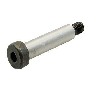
ASTM A574 Socket Head Shoulder Bolts, sometimes called stripper bolts or just shoulder bolts, have a smooth shoulder that is larger than the thread diameter, running down the majority of the length of the fastener. The shoulder, having a larger diameter than the threads allows the fastener to be used in rotating applications such as pulley shafts, bearing pins, axles, and pivot points. The thread length is standard for a given diameter. Unlike most fasteners, socket head shoulder bolts are not sized by the thread diameter and length under the head, rather the diameter and length of the shoulder itself. Dimensional specifications are governed by ASME B18.3.
Products
Dimensional Specifications

| Per ASME B18.3-2003 | |||||||||||||
| Size | Nominal | D | A | H | C | J | T | M | R | ||||
| Shoulder Diameter |
Head Diameter | Head Height | Chamfer or Radius |
Hexagon Socket Size |
Key Engage- ment |
Fillet Transition Diameter |
Head Fillet Radius |
||||||
| Max | Min | Max | Min | Max | Min | Max | Nom | Min | Max | Min | |||
| 1/4 | 0.2500 | 0.2480 | 0.2460 | 0.3750 | 0.3570 | 0.1880 | 0.1770 | 0.0200 | 1/8 | 0.1250 | 0.0940 | 0.2760 | 0.0090 |
| 5/16 | 0.3120 | 0.3105 | 0.3085 | 0.4380 | 0.4190 | 0.2190 | 0.2090 | 0.0260 | 5/32 | 0.1560 | 0.1170 | 0.3450 | 0.0120 |
| 3/8 | 0.3750 | 0.3730 | 0.3710 | 0.5620 | 0.5430 | 0.2500 | 0.2400 | 0.0310 | 3/16 | 0.1880 | 0.1410 | 0.4130 | 0.0150 |
| 1/2 | 0.5000 | 0.4980 | 0.4960 | 0.7500 | 0.7290 | 0.3120 | 0.3020 | 0.0400 | 1/4 | 0.2500 | 0.1880 | 0.5500 | 0.0200 |
| 5/8 | 0.6250 | 0.6230 | 0.6210 | 0.8750 | 0.8530 | 0.3750 | 0.3650 | 0.0500 | 5/16 | 0.3120 | 0.2340 | 0.6870 | 0.0240 |
| 3/4 | 0.7500 | 0.7480 | 0.7460 | 1.0000 | 0.9770 | 0.5000 | 0.4900 | 0.0600 | 3/8 | 0.3750 | 0.2810 | 0.8260 | 0.0300 |
| 1 | 1.0000 | 0.9980 | 0.9960 | 1.3120 | 1.2870 | 0.6250 | 0.6100 | 0.0830 | 1/2 | 0.5000 | 0.3750 | 1.0980 | 0.0400 |
| 1 1/4 | 1.2500 | 1.2480 | 1.2460 | 1.7500 | 1.7230 | 0.7500 | 0.7350 | 0.1020 | 5/8 | 0.6250 | 0.4690 | 1.3680 | 0.0500 |
| 1 1/2 | 1.5000 | 1.4980 | 1.4960 | 2.1250 | 2.0950 | 1.0000 | 0.9800 | 0.1380 | 7/8 | 0.8750 | 0.6560 | 1.6380 | 0.0600 |
| 1 3/4 | 1.7500 | 1.7480 | 1.7460 | 2.3750 | 2.3450 | 1.1250 | 1.1050 | 0.1570 | 1 | 1.0000 | 0.7500 | 1.9080 | 0.0700 |
| 2 | 2.0000 | 1.9980 | 1.9960 | 2.7500 | 2.7200 | 1.2500 | 1.2300 | 0.1760 | 1 1/4 | 1.2500 | 0.9370 | 2.1780 | 0.0800 |
| See Notes | 1 | 8 | 6 | ||||||||||
| Size | Nominal | K | F | D1 | G | I | N | E | P | ||||
| Shoulder Neck Diameter |
Shoulder Neck Width |
Nominal Thread Diameter |
Threads per Inch |
Thread Neck Diameter |
Thread Neck Width |
Thread Neck Fillet |
Thread Length |
Chamfer or Radius |
|||||
| Min | Max | Max | Min | Max | Max | Min | Basic | Max | |||||
| 1/4 | 0.2500 | 0.2270 | 0.0930 | #10 | 0.1900 | 24 | 0.142 | 0.133 | 0.083 | 0.023 | 0.017 | 0.375 | 0.010 |
| 5/16 | 0.3120 | 0.2890 | 0.0930 | 1/4 | 0.2500 | 20 | 0.193 | 0.182 | 0.100 | 0.028 | 0.022 | 0.438 | 0.010 |
| 3/8 | 0.3750 | 0.3520 | 0.0930 | 5/16 | 0.3125 | 18 | 0.249 | 0.237 | 0.111 | 0.031 | 0.025 | 0.500 | 0.010 |
| 1/2 | 0.5000 | 0.4770 | 0.0930 | 3/8 | 0.3750 | 6 | 0.304 | 0.291 | 0.125 | 0.035 | 0.029 | 0.625 | 0.010 |
| 5/8 | 0.6250 | 0.6020 | 0.0930 | 1/2 | 0.5000 | 13 | 0.414 | 0.397 | 0.154 | 0.042 | 0.036 | 0.750 | 0.015 |
| 3/4 | 0.7500 | 0.7270 | 0.0930 | 5/8 | 0.6250 | 11 | 0.521 | 0.502 | 0.182 | 0.051 | 0.045 | 0.875 | 0.015 |
| 1 | 1.0000 | 0.9770 | 0.1250 | 3/4 | 0.7500 | 10 | 0.638 | 0.616 | 0.200 | 0.056 | 0.049 | 1.000 | 0.020 |
| 1 1/4 | 1.2500 | 1.2270 | 0.1250 | 7/8 | 0.8750 | 9 | 0.750 | 0.726 | 0.222 | 0.062 | 0.056 | 1.125 | 0.020 |
| 1 1/2 | 1.5000 | 1.4780 | 0.1250 | 1 1/8 | 1.1250 | 7 | 0.964 | 0.934 | 0.286 | 0.072 | 0.066 | 1.500 | 0.020 |
| 1 3/4 | 1.7500 | 1.7280 | 0.1250 | 1 1/4 | 1.2500 | 7 | 1.089 | 1.059 | 0.286 | 0.072 | 0.066 | 1.750 | 0.020 |
| 2 | 2.0000 | 1.9780 | 0.1250 | 1 1/2 | 1.5000 | 6 | 1.307 | 1.277 | 0.333 | 0.102 | 0.096 | 2.000 | 0.020 |
| See Notes | 6 | 6 | 10 | 7 | 7 | 7 | |||||||
- 1. Shoulder. Shoulder refers to the enlarged unthreaded portion of the screw, the diameter of which serves as the basis for derivation of the nominal size.
- 6. Neck and Fillet Under Head. Screws may be necked under the head at the option of the manufacturer. The fillet extension above D, at the intersection of the head bearing surface and neck or shoulder, shall be controlled by maximum dimension M and minimum radius of curvature R. (See Detail Y)
- 7. Neck Under Shoulder. The neck under the shoulder shall allow the shoulder to seat against the face of a standard basic GO thread ring gage.
- 8. Head Diameter. The head may be plain or knurled at the option of the manufacturer.
- 10. Threads. Threads shall be Unified external thread: Class 3A, UNC Series. Acceptability is to be based on System 22, ASME B1.3M. Class 3A does not provide a plating allowance. When plated products are required, it is recommended that they be procured from the manufacturer.
Mechanical Properties
| Alloy Steel, Quenched & Tempered | Per ASTM A574-13 | ||||||
| Nominal Diameter |
Full-Size Screws | Machined Test Specimen | Product Hardness |
||||
| Tensile Strength |
Proof Load |
Yield Strength at 0.2% offset |
Tensile Strength |
Elongation in 5D |
Reduction of Area |
||
| ksi | ksi | ksi | ksi | % | % | Rockwell | |
| 1/2" & under | 180 min | 140 | 153 min | 180 min | 10 min | 35 min | 39-45 HRC |
| over 1/2" | 170 min | 135 | 153 min | 170 min | 10 min | 35 min | 37-45 HRC |
Governing Standards
| ASTM A574 | Covers the requirements for quenched and tempered alloy steel hexagon socket-head cap screws, 0.060 through 4 in. in diameter where high strength is required. |
| ASME B18.3 | Covers the complete general and dimensional data for various types of hexagon socket cap screws, shoulder screws, set screws, and hexagon keys recognized as an American National Standard. |
| ASME B1.1 UNC & UNF Class 2A | Specifies the thread form, series, class, allowance, tolerance, and designation for unified screw threads. |

Alloy Steel Socket Shoulder Bolt requires no material marking
Chemical Properties
| Per ASTM A574-13 | ||||||||
| Material | Heat Analysis | Product Analysis | ||||||
| Carbon | Phosphorus | Sulfur | Alloying Elements |
Carbon | Phosphorus | Sulfur | Alloying Elements |
|
| % by weight | % by weight | % by weight | % by weight | % by weight | % by weight | |||
| Quenched and tempered alloy steel |
0.33 min | 0.035 max | 0.040 max | (1) | 0.31 min | 0.040 max | 0.045 max | (1) |
- 1. One or more of the following alloying elements: chromium, nickel, molybdenum, or vanadium shall be present in sufficient quantity to ensure that the specified strength properties are met after oil quenching and tempering. As a guide for selecting material, an alloy steel should be capable of meeting the specified mechanical requirements if the “as oil quenched” core hardness one diameter from the point is equal to or exceeds 25 HRC + (55 × carbon content).