
Dti Washer, Galvanized
Dti Washer, Galvanized
Manufacturers:
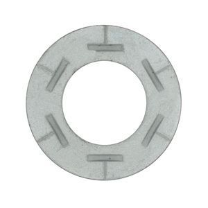
ASTM F959, Type A325 Direct Tension Indicator (DTI) washers are used to indicate the correct bolt tension when an A325 structural bolt is installed. The DTI is placed under a hardened surface such as a bolt head, nut, or hardened washer, with the bumps facing away from the structural steel. As the bolt is tensioned, the clamping force flattens the bumps, reducing the gap. The operator then checks the gap between the bumps to ensure the bumps have been crushed to within a determined tolerance, which results in the bolt reaching its proper tension. Dimensional specifications are governed by ASME B18.2.6. Available in mechanical galvanized finish, which provides a corrosion resistant zinc coating.
Products
Governing Standards
| ASTM F959 | Covers the requirements for compressible-washer-type direct tension indicators capable of indicating the achievement of a specified minimum bolt tension in a structural bolt. |
| ASME B18.2.6 | Covers the general and dimensional data for five products in the inch series recognized as American National Standard. These five structural products include: (a) Heavy Hex Structural Bolts: ASTM A325 or ASTM A490; (b) Heavy Hex Nuts: ASTM A563; (c) Hardened Steel Washers; Circular, Circular Clipped or Beveled: ASTM F436; (d) Compressible Washer-Type Direct Tension Indicators: ASTM F959; (e) Twist-Off-Type Tension Control Structural Bolts: Heavy Hex and Round: ASTM F1852. |
Chemical Properties
| Per ASTM F959-2009 | |||||
| Grade | Carbon | Manganese | Phosphorus | Sulfur | Silicon |
| % by weight | % by weight | % by weight | % by weight | % by weight | |
| DTI - Type 325 | 0.30-0.55 | 0.50-0.90 | 0.04 | 0.045 | 0.15-0.35 |
Mechanical Properties
| Per ASTM F959-2009 | |
| Acceptable Range of Compression Loads |
|
| Size | Type A325 (1000 lbs) |
| 1/2 | 12-14 |
| 5/8 | 19-23 |
| 3/4 | 28-34 |
| 7/8 | 39-47 |
| 1 | 51-61 |
| 1 1/8 | 56-67 |
| 1 1/4 | 71-85 |
| 1 3/8 | 85-102 |
| 1 1/2 | 103-124 |
Dimensional Specifications

| Per ASME B18.2.6-2011 | ||||||||
| Size | A | B | C | Number of Protrusions (Equally Spaced) |
E | F | ||
| Inside Diameter |
Protrusion Tangential Diameter |
Outside Diameter |
Thickness | |||||
| Without Protrusion |
With Protrusion |
|||||||
| Min | Max | Max | Min | Max | Min | Max | ||
| 1/2 | 0.523 | 0.527 | 0.788 | 1.167 | 1.187 | 4 | 0.104 | 0.180 |
| 5/8 | 0.654 | 0.658 | 0.956 | 1.355 | 1.375 | 4 | 0.126 | 0.220 |
| 3/4 | 0.786 | 0.790 | 1.125 | 1.605 | 1.625 | 5 | 0.126 | 0.230 |
| 7/8 | 0.917 | 0.921 | 1.294 | 1.855 | 1.875 | 5 | 0.142 | 0.240 |
| 1 | 1.048 | 1.052 | 1.463 | 1.980 | 2.000 | 6 | 0.158 | 0.270 |
| 1 1/8 | 1.179 | 1.183 | 1.631 | 2.230 | 2.250 | 6 | 0.158 | 0.270 |
| 1 1/4 | 1.311 | 1.315 | 1.800 | 2.480 | 2.500 | 7 | 0.158 | 0.270 |
| 1 3/8 | 1.442 | 1.446 | 1.969 | 2.730 | 2.750 | 7 | 0.158 | 0.270 |
| 1 1/2 | 1.573 | 1.577 | 2.138 | 2.980 | 3.000 | 8 | 0.158 | 0.270 |
- All dimensions are in inches.