
Lifting Eye Bolt
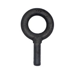
Lifting Eye Bolt
Manufacturers:
ASTM A489 Type 1 Lifting Eye Bolts are forged, carbon steel threaded eye bolts intended for use with tapped holes that have been engineered as a lifting point. Dimensional specifications are governed by ASME B18.15 in sizes 1/4" through 2-1/2". According to ASME B30.26 - Rigging Hardware, each eye bolt shall be marked to show: 1. Name or trademark of manufacturer, 2. Size or rated load and 3. Grade for alloy eye bolts.
Products
Governing Standards
| ASTM A489 | Covers weldless forged, quenched, and tempered carbon steel threaded lifting eyes (formerly eyebolts) for overhead lifting. |
| ASME B18.15 | Covers dimensions and capacities for carbon and stainless steel forged threaded eyebolts in sizes ¼ through 2-1/2 inch for steel and ¼ through 1-1/2” for corrosion resistant stainless steel intended primarily for lifting applications. |
| ASME B1.1 UNC Class 2A |
Specifies the thread form, series, class, allowance, tolerance, and designation for unified screw threads. |
Chemical Properties
| Per ASTM A489-12 | |||||
| Analysis Type | Carbon | Manganese | Phosphorus | Sulfur | Silicon |
| Max | Max | Max | Max | % by weight | |
| Heat Analysis | 0.48 | 1.00 | 0.040 | 0.050 | 0.15 - 0.35 |
| Product Analysis | 0.51 | 1.06 | 0.048 | 0.058 | 0.12 - 0.38 |
Load Ratings
| Weldless Forged, Quenched and Tempered Carbon Steel | Per ASTM A489-12 | ||||
| Nominal Thread Size |
Thread Pitch |
Tensile Stress AreaA |
Breaking Strength | Proof LoadB | *Rated Capacity lbs |
| Min | Min | ||||
| Inch Pound Units | |||||
| in. | in.2 | lbf | lbf | ||
| 1/4 | 20 | 0.0318 | 2 100 | 800 | 500 |
| 5/16 | 18 | 0.0524 | 3 400 | 1 360 | 900 |
| 3/8 | 16 | 0.0775 | 5 000 | 2 000 | 1,300 |
| 7/16 | 14 | 0.1063 | 6 900 | 2 760 | 1,800 |
| 1/2 | 13 | 0.1419 | 9 200 | 3 680 | 2,400 |
| 9/16 | 12 | 0.1820 | 11 830 | 4 740 | 3,000 |
| 5/8 | 11 | 0.2260 | 14 700 | 5 880 | 4,000 |
| 3/4 | 10 | 0.3340 | 21 700 | 8 680 | 5,000 |
| 7/8 | 9 | 0.4620 | 30 000 | 12 000 | 7,000 |
| 1 | 8 | 0.6060 | 39 400 | 15 760 | 9,000 |
| 1 1/8 | 7 | 0.7630 | 49 600 | 19 840 | 12,000 |
| 1 1/4 | 7 | 0.9690 | 63 000 | 25 200 | 15,000 |
| 1 1/2 | 6 | 1.4100 | 91 600 | 36 520 | 21,000 |
| 1 3/4 | 5 | 1.9000 | 123 500 | 49 400 | 28,000 |
| 2 | 4 | 2.5000 | 162 500 | 65 000 | 38,000 |
| 2 1/2 | 4 | 4.0000 | 260 000 | 104 000 | 56,000 |
- AThe stress area is calculated as follows: As=0.7854 [D - (0.9743/n)]2
- Where:
- As = stress area, in.2,
- D = nominal bolt size, and
- n = threads per inch.
- BProof load is calculated as 2 times the rated capacity in straight pull (0 degrees) specified in ASME B18.15.
- *NOTE: Rated capacity is for zero degree vertical pulls. Please Shoulder Eyebolt Rated Capacity/Guidelines for complete lifting information. Swivel Hoist Rings are recommended for angular lifts. Per ASME B18.15-1985 (R1995).
Mechanical Properties
| Weldless Forged, Quenched and Tempered Carbon Steel | Per ASTM A489-12 | ||||
| Tensile Strength |
Tensile Strength |
Yield Point | Yield Point | Elongation in 4D |
Reduction of Area |
| psi | (MPa) | Min psi | Min (MPa) | Min % | Min % |
| 65 000-90 000 | (448-620) | 30 000 | -207 | 30 | 60 |
Dimensional Specifications

| Per ASME B18.15-1985 (R1995) | |||||||||||||||||
| Nominal Diameter |
UNC | A | B | C | D | E | F | G | H | J | |||||||
| Shank Diameter |
Shank Length | Eye Inside Diameter |
Eye Outside Diameter |
Overall Length | Eye Section Diameter |
Shoulder Diameter |
Shoulder Thickness |
Eye to Shoulder |
|||||||||
| Min | Max | Min | Max | Min | Max | Min | Max | Min | Max | Min | Max | Min | Max | ||||
| 1/4 | 20 | 0.25 | 1.00 | 1.06 | 0.69 | 0.81 | 1.19 | 2.22 | 2.53 | 0.19 | 0.25 | 0.50 | 0.56 | 0.12 | 0.19 | 0.69 | 0.81 |
| 5/16 | 18 | 0.31 | 1.12 | 1.19 | 0.81 | 0.94 | 1.44 | 2.66 | 2.97 | 0.25 | 0.31 | 0.56 | 0.62 | 0.12 | 0.19 | 0.88 | 1.00 |
| 3/8 | 16 | 0.38 | 1.25 | 1.38 | 0.94 | 1.06 | 1.69 | 3.09 | 3.47 | 0.31 | 0.38 | 0.62 | 0.69 | 0.12 | 0.19 | 1.06 | 1.19 |
| 7/16 | 14 | 0.44 | 1.38 | 1.50 | 1.00 | 1.12 | 1.81 | 3.41 | 3.78 | 0.34 | 0.41 | 0.75 | 0.81 | 0.19 | 0.25 | 1.19 | 1.31 |
| 1/2 | 13 | 0.50 | 1.50 | 1.62 | 1.12 | 1.25 | 2.12 | 3.81 | 4.19 | 0.44 | 0.50 | 0.88 | 0.94 | 0.19 | 0.25 | 1.31 | 1.44 |
| 9/16 | 12 | 0.56 | 1.62 | 1.75 | 1.19 | 1.31 | 2.25 | 4.19 | 4.56 | 0.47 | 0.53 | 0.94 | 1.00 | 0.22 | 0.28 | 1.50 | 1.62 |
| 5/8 | 11 | 0.62 | 1.75 | 1.88 | 1.31 | 1.44 | 2.56 | 4.56 | 4.94 | 0.56 | 0.62 | 1.00 | 1.06 | 0.25 | 0.31 | 1.59 | 1.72 |
| 3/4 | 10 | 0.75 | 2.00 | 2.12 | 1.44 | 1.56 | 2.81 | 5.06 | 5.50 | 0.62 | 0.69 | 1.12 | 1.25 | 0.25 | 0.31 | 1.72 | 1.91 |
| 7/8 | 9 | 0.88 | 2.25 | 2.38 | 1.56 | 1.69 | 3.19 | 5.75 | 6.19 | 0.75 | 0.81 | 1.31 | 1.44 | 0.31 | 0.38 | 2.03 | 2.22 |
| 1 | 8 | 1.00 | 2.50 | 2.62 | 1.69 | 1.81 | 3.56 | 6.44 | 6.88 | 0.88 | 0.94 | 1.50 | 1.62 | 0.38 | 0.44 | 2.22 | 2.41 |
| 1 1/8 | 7 | 1.12 | 2.75 | 2.88 | 1.94 | 2.06 | 4.06 | 7.31 | 7.75 | 1.00 | 1.06 | 1.69 | 1.81 | 0.44 | 0.50 | 2.59 | 2.78 |
| 1 1/4 | 7 | 1.25 | 3.00 | 3.12 | 2.12 | 2.25 | 4.44 | 8.00 | 8.44 | 1.09 | 1.16 | 1.88 | 2.00 | 0.50 | 0.56 | 2.84 | 3.03 |
| 1 1/2 | 6 | 1.50 | 3.50 | 3.62 | 2.44 | 2.56 | 5.19 | 9.22 | 9.72 | 1.31 | 1.38 | 2.12 | 2.25 | 0.50 | 0.62 | 3.19 | 3.44 |
| 1 3/4 | 5 | 1.75 | 3.75 | 3.88 | 2.75 | 3.00 | 6.00 | 10.50 | 11.12 | 1.50 | 1.62 | 2.50 | 2.62 | 0.50 | 0.62 | 3.88 | 4.12 |
| 2 | 4.5 | 2.00 | 4.00 | 4.12/4.25 | 3.06 | 3.44 | 6.88 | 11.53 | 12.22 | 1.75 | 1.88 | 2.88 | 3.00 | 0.62 | 0.75 | 4.25 | 4.50 |
| 2 1/2 | 4 | 2.50 | 5.00 | 5.25 | 3.81 | 4.19 | 8.50 | 14.59 | 15.40 | 2.19 | 2.31 | 3.62 | 3.75 | 0.88 | 1.00 | 5.50 | 5.75 |
- All dimensions are in inches.