
Shoulder Lifting Eye Bolt Domestic
Shoulder Lifting Eye Bolt Domestic
Manufacturers:
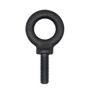
ASTM A489 Type 2 Shoulder Lifting Eye Bolts are forged, carbon steel threaded eye bolts intended for use with tapped holes that have been engineered as a lifting point. When equipped with a shoulder, these eye bolts can be used with angular loads up to 45°. Dimensional specifications are governed by ASME B18.15 in sizes 1/4" through 2-1/2". According to ASME B30.26 - Rigging Hardware, each eye bolt shall be marked to show: 1. Name or trademark of manufacturer, 2. Size or rated load and 3. Grade for alloy eye bolts. Eye bolts listed below are melted and manufactured in the USA.
Products
Chemical Properties
| Per ASTM A489-12 | |||||
| Analysis Type | Carbon | Manganese | Phosphorus | Sulfur | Silicon |
| Max | Max | Max | Max | % by weight | |
| Heat Analysis | 0.48 | 1.00 | 0.040 | 0.050 | 0.15 - 0.35 |
| Product Analysis | 0.51 | 1.06 | 0.048 | 0.058 | 0.12 - 0.38 |
Dimensional Specifications

| Per ASME B18.15-1985 (R1995) | |||||||||||||||||
| Nominal Diameter |
UNC | A | B | C | D | E | F | G | H | J | |||||||
| Shank Diameter |
Shank Length | Eye Inside Diameter |
Eye Outside Diameter |
Overall Length | Eye Section Diameter |
Shoulder Diameter |
Shoulder Thickness |
Eye to Shoulder |
|||||||||
| Min | Max | Min | Max | Min | Max | Min | Max | Min | Max | Min | Max | Min | Max | ||||
| 1/4 | 20 | 0.25 | 1.00 | 1.06 | 0.69 | 0.81 | 1.19 | 2.22 | 2.53 | 0.19 | 0.25 | 0.50 | 0.56 | 0.12 | 0.19 | 0.69 | 0.81 |
| 5/16 | 18 | 0.31 | 1.12 | 1.19 | 0.81 | 0.94 | 1.44 | 2.66 | 2.97 | 0.25 | 0.31 | 0.56 | 0.62 | 0.12 | 0.19 | 0.88 | 1.00 |
| 3/8 | 16 | 0.38 | 1.25 | 1.38 | 0.94 | 1.06 | 1.69 | 3.09 | 3.47 | 0.31 | 0.38 | 0.62 | 0.69 | 0.12 | 0.19 | 1.06 | 1.19 |
| 7/16 | 14 | 0.44 | 1.38 | 1.50 | 1.00 | 1.12 | 1.81 | 3.41 | 3.78 | 0.34 | 0.41 | 0.75 | 0.81 | 0.19 | 0.25 | 1.19 | 1.31 |
| 1/2 | 13 | 0.50 | 1.50 | 1.62 | 1.12 | 1.25 | 2.12 | 3.81 | 4.19 | 0.44 | 0.50 | 0.88 | 0.94 | 0.19 | 0.25 | 1.31 | 1.44 |
| 9/16 | 12 | 0.56 | 1.62 | 1.75 | 1.19 | 1.31 | 2.25 | 4.19 | 4.56 | 0.47 | 0.53 | 0.94 | 1.00 | 0.22 | 0.28 | 1.50 | 1.62 |
| 5/8 | 11 | 0.62 | 1.75 | 1.88 | 1.31 | 1.44 | 2.56 | 4.56 | 4.94 | 0.56 | 0.62 | 1.00 | 1.06 | 0.25 | 0.31 | 1.59 | 1.72 |
| 3/4 | 10 | 0.75 | 2.00 | 2.12 | 1.44 | 1.56 | 2.81 | 5.06 | 5.50 | 0.62 | 0.69 | 1.12 | 1.25 | 0.25 | 0.31 | 1.72 | 1.91 |
| 7/8 | 9 | 0.88 | 2.25 | 2.38 | 1.56 | 1.69 | 3.19 | 5.75 | 6.19 | 0.75 | 0.81 | 1.31 | 1.44 | 0.31 | 0.38 | 2.03 | 2.22 |
| 1 | 8 | 1.00 | 2.50 | 2.62 | 1.69 | 1.81 | 3.56 | 6.44 | 6.88 | 0.88 | 0.94 | 1.50 | 1.62 | 0.38 | 0.44 | 2.22 | 2.41 |
| 1 1/8 | 7 | 1.12 | 2.75 | 2.88 | 1.94 | 2.06 | 4.06 | 7.31 | 7.75 | 1.00 | 1.06 | 1.69 | 1.81 | 0.44 | 0.50 | 2.59 | 2.78 |
| 1 1/4 | 7 | 1.25 | 3.00 | 3.12 | 2.12 | 2.25 | 4.44 | 8.00 | 8.44 | 1.09 | 1.16 | 1.88 | 2.00 | 0.50 | 0.56 | 2.84 | 3.03 |
| 1 1/2 | 6 | 1.50 | 3.50 | 3.62 | 2.44 | 2.56 | 5.19 | 9.22 | 9.72 | 1.31 | 1.38 | 2.12 | 2.25 | 0.50 | 0.62 | 3.19 | 3.44 |
| 1 3/4 | 5 | 1.75 | 3.75 | 3.88 | 2.75 | 3.00 | 6.00 | 10.50 | 11.12 | 1.50 | 1.62 | 2.50 | 2.62 | 0.50 | 0.62 | 3.88 | 4.12 |
| 2 | 4.5 | 2.00 | 4.00 | 4.12/4.25 | 3.06 | 3.44 | 6.88 | 11.53 | 12.22 | 1.75 | 1.88 | 2.88 | 3.00 | 0.62 | 0.75 | 4.25 | 4.50 |
| 2 1/2 | 4 | 2.50 | 5.00 | 5.25 | 3.81 | 4.19 | 8.50 | 14.59 | 15.40 | 2.19 | 2.31 | 3.62 | 3.75 | 0.88 | 1.00 | 5.50 | 5.75 |
- All dimensions are in inches.
Mechanical Properties
| Weldless Forged, Quenched and Tempered Carbon Steel | Per ASTM A489-12 | ||||
| Tensile Strength |
Tensile Strength |
Yield Point | Yield Point | Elongation in 4D |
Reduction of Area |
| psi | (MPa) | Min psi | Min (MPa) | Min % | Min % |
| 65 000-90 000 | (448-620) | 30 000 | -207 | 30 | 60 |
Governing Standards
| ASTM A489 | Covers weldless forged, quenched, and tempered carbon steel threaded lifting eyes (formerly eyebolts) for overhead lifting. |
| ASME B18.15 | Covers dimensions and capacities for carbon and stainless steel forged threaded eyebolts in sizes ¼ through 2-1/2 inch for steel and ¼ through 1-1/2” for corrosion resistant stainless steel intended primarily for lifting applications. |
| ASME B1.1 UNC Class 2A |
Specifies the thread form, series, class, allowance, tolerance, and designation for unified screw threads. |
Load Ratings
| Weldless Forged, Quenched and Tempered Carbon Steel | Per ASTM A489-12 | ||||
| Nominal Thread Size |
Thread Pitch |
Tensile Stress AreaA |
Breaking Strength | Proof LoadB | *Rated Capacity lbs |
| Min | Min | ||||
| Inch Pound Units | |||||
| in. | in.2 | lbf | lbf | ||
| 1/4 | 20 | 0.0318 | 2 100 | 800 | 500 |
| 5/16 | 18 | 0.0524 | 3 400 | 1 360 | 900 |
| 3/8 | 16 | 0.0775 | 5 000 | 2 000 | 1,300 |
| 7/16 | 14 | 0.1063 | 6 900 | 2 760 | 1,800 |
| 1/2 | 13 | 0.1419 | 9 200 | 3 680 | 2,400 |
| 9/16 | 12 | 0.1820 | 11 830 | 4 740 | 3,000 |
| 5/8 | 11 | 0.2260 | 14 700 | 5 880 | 4,000 |
| 3/4 | 10 | 0.3340 | 21 700 | 8 680 | 5,000 |
| 7/8 | 9 | 0.4620 | 30 000 | 12 000 | 7,000 |
| 1 | 8 | 0.6060 | 39 400 | 15 760 | 9,000 |
| 1 1/8 | 7 | 0.7630 | 49 600 | 19 840 | 12,000 |
| 1 1/4 | 7 | 0.9690 | 63 000 | 25 200 | 15,000 |
| 1 1/2 | 6 | 1.4100 | 91 600 | 36 520 | 21,000 |
| 1 3/4 | 5 | 1.9000 | 123 500 | 49 400 | 28,000 |
| 2 | 4 | 2.5000 | 162 500 | 65 000 | 38,000 |
| 2 1/2 | 4 | 4.0000 | 260 000 | 104 000 | 56,000 |
- AThe stress area is calculated as follows: As=0.7854 [D - (0.9743/n)]2
- Where:
- As = stress area, in.2,
- D = nominal bolt size, and
- n = threads per inch.
- BProof load is calculated as 2 times the rated capacity in straight pull (0 degrees) specified in ASME B18.15.
- *NOTE: Rated capacity is for zero degree vertical pulls. Please Shoulder Eyebolt Rated Capacity/Guidelines for complete lifting information. Swivel Hoist Rings are recommended for angular lifts. Per ASME B18.15-1985 (R1995).