
1 1/2'' #600 A105 Raised Face Blind Flange North America
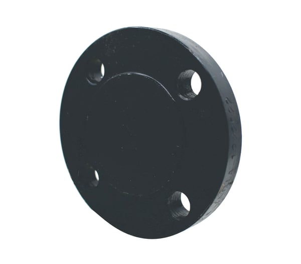
1 1/2'' #600 A105 Raised Face Blind Flange North America
Item #: PBL60RFC1.5-NU
Manufacturers:
Product Specification
| Grade | A105 |
|---|---|
| Pipe Diameter | 1 1/2 |
| Flange Rating | 600# |
| Outside Diameter | 6.1200 |
| Bolt Hole Circle | 4.5000 |
| # of Bolt Holes | 4 |
| Bolt Hole Diameter | 7/8 |
| Material | Steel |
| Finish | Black |
| Country of Origin | North America |
| Weight | 8.000000 |
Mechanical Properties
| Per ASTM A105-A105M - 24 | |||||
| Grade A105 | Tensile Strength | Yield Strength | Elongation in 4D | Reduction in Area | Hardness |
| Min ksi [MPa] | Min ksi [Mpa] | Min % | Min % | Max | |
| 70 [485] | 36 [250] | 22 | 30 | 197 |
Dimensional Specifications


Class #150 Dimensions |
Drilling | Length of Bolts | |||||||
| Pipe Size | Outside Diameter of Flange | Thickness of Flange (Min.) | Diameter of Bolt Circle | Diameter of Bolt Holes | Number of Bolt Holes | Diameter of Bolts | Stud Bolts Raised Face 0.06 in. | Stud Bolts Ring Joint | Machine Bolts Raised Face 0.06 in. |
| O.D. | C | M | P | P | P | ||||
| 1/2 | 3.50 | 0.38 | 2.38 | 5/8 | 4 | 1/2 | 2.25 | 2.00 | |
| 3/4 | 3.88 | 0.44 | 2.75 | 5/8 | 4 | 1/2 | 2.50 | 2.00 | |
| 1 | 4.25 | 0.50 | 3.12 | 5/8 | 4 | 1/2 | 2.50 | 3.00 | 2.25 |
| 1 1/4 | 4.62 | 0.56 | 3.50 | 5/8 | 4 | 1/2 | 2.75 | 3.25 | 2.25 |
| 1 1/2 | 5.00 | 0.62 | 3.88 | 5/8 | 4 | 1/2 | 2.75 | 3.25 | 2.50 |
| 2 | 6.00 | 0.69 | 4.75 | 3/4 | 4 | 5/8 | 3.25 | 3.75 | 2.75 |
| 2 1/2 | 7.00 | 0.81 | 5.50 | 3/4 | 4 | 5/8 | 3.50 | 4.00 | 3.00 |
| 3 | 7.50 | 0.88 | 6.00 | 3/4 | 4 | 5/8 | 3.50 | 4.00 | 3.00 |
| 3 1/2 | 8.50 | 0.88 | 7.00 | 3/4 | 8 | 5/8 | 3.50 | 4.00 | 3.00 |
| 4 | 9.00 | 0.88 | 7.50 | 3/4 | 8 | 5/8 | 3.50 | 4.00 | 3.00 |
| 5 | 10.00 | 0.88 | 8.50 | 7/8 | 8 | 3/4 | 3.75 | 4.25 | 3.25 |
| 6 | 11.00 | 0.94 | 9.50 | 7/8 | 8 | 3/4 | 4.00 | 4.50 | 3.25 |
| 8 | 13.50 | 1.06 | 11.75 | 7/8 | 8 | 3/4 | 4.25 | 4.75 | 3.50 |
| 10 | 16.00 | 1.12 | 14.25 | 1 | 12 | 7/8 | 4.50 | 5.00 | 4.00 |
| 12 | 19.00 | 1.19 | 17.00 | 1 | 12 | 7/8 | 4.75 | 5.25 | 4.00 |
| 14 | 21.00 | 1.31 | 18.75 | 1 1/8 | 12 | 1 | 5.25 | 5.75 | 4.50 |
| 16 | 23.50 | 1.38 | 21.25 | 1 1/8 | 16 | 1 | 5.25 | 5.75 | 4.50 |
| 18 | 25.00 | 1.50 | 22.75 | 1 1/4 | 16 | 1 1/8 | 5.75 | 6.25 | 5.00 |
| 20 | 27.50 | 1.62 | 25.00 | 1 1/4 | 20 | 1 1/8 | 6.25 | 6.75 | 5.50 |
| 24 | 32.00 | 1.81 | 29.50 | 1 3/8 | 20 | 1 1/8 | 6.75 | 7.25 | 6.00 |
Class #300 Dimensions |
Drilling | Length of Bolts | |||||||
| Pipe Size | Outside Diameter of Flange | Thickness of Flange (Min.) | Diameter of Bolt Circle | Diameter of Bolt Holes | Number of Bolt Holes | Diameter of Bolts | Stud Bolts Raised Face 0.06 in. | Stud Bolts Ring Joint | Machine Bolts Raised Face 0.06 in. |
| O.D. | C | M | P | P | P | ||||
| 1/2 | 3.75 | 0.5 | 2.62 | 5/8 | 4 | 1/2 | 2.50 | 3.00 | 2.25 |
| 3/4 | 4.62 | 0.56 | 3.25 | 3/4 | 4 | 5/8 | 3.00 | 3.50 | 2.50 |
| 1 | 4.88 | 0.62 | 3.5 | 3/4 | 4 | 5/8 | 3.00 | 3.50 | 2.50 |
| 1 1/4 | 5.25 | 0.69 | 3.88 | 3/4 | 4 | 5/8 | 3.25 | 3.75 | 2.75 |
| 1 1/2 | 6.12 | 0.75 | 4.50 | 7/8 | 4 | 3/4 | 3.50 | 4.00 | 3.00 |
| 2 | 6.50 | 0.81 | 5.00 | 3/4 | 8 | 5/8 | 3.50 | 4.00 | 3.00 |
| 2 1/2 | 7.50 | 0.94 | 5.88 | 7/8 | 8 | 3/4 | 4.00 | 4.50 | 3.25 |
| 3 | 8.25 | 1.06 | 6.62 | 7/8 | 8 | 3/4 | 4.25 | 4.75 | 3.50 |
| 3 1/2 | 9.00 | 1.12 | 7.25 | 7/8 | 8 | 3/4 | 4.25 | 5.00 | 3.75 |
| 4 | 10.00 | 1.19 | 7.88 | 7/8 | 8 | 3/4 | 4.50 | 5.00 | 3.75 |
| 5 | 11.00 | 1.31 | 9.25 | 7/8 | 8 | 3/4 | 4.75 | 5.25 | 4.25 |
| 6 | 12.50 | 1.38 | 10.62 | 7/8 | 12 | 3/4 | 4.75 | 5.50 | 4.25 |
| 8 | 15.00 | 1.56 | 13.00 | 1 | 12 | 7/8 | 5.50 | 6.00 | 4.75 |
| 10 | 17.50 | 1.81 | 15.25 | 1 1/8 | 16 | 1 | 6.25 | 6.75 | 5.50 |
| 12 | 20.50 | 1.94 | 17.75 | 1 1/4 | 16 | 1 1/8 | 6.75 | 7.25 | 5.75 |
| 14 | 23.00 | 2.06 | 20.25 | 1 1/4 | 20 | 1 1/8 | 7.00 | 7.50 | 6.25 |
| 16 | 25.50 | 2.19 | 22.50 | 1 3/8 | 20 | 1 1/4 | 7.50 | 8.00 | 6.50 |
| 18 | 28.00 | 2.31 | 24.75 | 1 3/8 | 24 | 1 1/4 | 7.75 | 8.25 | 6.75 |
| 20 | 30.50 | 2.44 | 27.00 | 1 3/8 | 24 | 1 1/4 | 8.00 | 8.75 | 7.25 |
| 24 | 36.00 | 2.69 | 32.00 | 1 5/8 | 24 | 1 1/2 | 9.00 | 10.00 | 8.00 |
Class #600 Dimensions |
Drilling | Length of Bolts | |||||||
| Pipe Size | Outside Diameter of Flange | Thickness of Flange (Min.) | Diameter of Bolt Circle | Diameter of Bolt Holes | Number of Bolt Holes | Diameter of Bolts | Raised Face 0.25 in. | Tongue & Groove | Ring Joint |
| O.D. | C | M | P | P | P | ||||
| 1/2 | 3.75 | 0.56 | 2.62 | 5/8 | 4 | 1/2 | 3.00 | 2.75 | 3.00 |
| 3/4 | 4.62 | 0.62 | 3.25 | 3/4 | 4 | 5/8 | 3.50 | 3.25 | 3.50 |
| 1 | 4.88 | 0.69 | 3.50 | 3/4 | 4 | 5/8 | 3.50 | 3.25 | 3.50 |
| 1 1/4 | 5.25 | 0.81 | 3.88 | 3/4 | 4 | 5/8 | 3.75 | 3.50 | 3.75 |
| 1 1/2 | 6.12 | 0.88 | 4.50 | 7/8 | 4 | 3/4 | 4.25 | 4.00 | 4.25 |
| 2 | 6.50 | 1.00 | 5.00 | 3/4 | 8 | 5/8 | 4.25 | 4.00 | 4.25 |
| 2 1/2 | 7.50 | 1.12 | 5.88 | 7/8 | 8 | 3/4 | 4.75 | 4.50 | 4.75 |
| 3 | 8.25 | 1.25 | 6.62 | 7/8 | 8 | 3/4 | 5.00 | 4.75 | 5.00 |
| 3 1/2 | 9.00 | 1.38 | 7.25 | 1 | 8 | 7/8 | 5.50 | 5.25 | 5.50 |
| 4 | 10.75 | 1.50 | 8.50 | 1 | 8 | 7/8 | 5.75 | 5.50 | 5.75 |
| 5 | 13.00 | 1.75 | 10.50 | 1 1/8 | 8 | 1 | 6.50 | 6.25 | 6.50 |
| 6 | 14.00 | 1.88 | 11.50 | 1 1/8 | 12 | 1 | 6.75 | 6.50 | 6.75 |
| 8 | 16.50 | 2.19 | 13.75 | 1 1/4 | 12 | 1 1/8 | 7.50 | 7.25 | 7.75 |
| 10 | 20.00 | 2.50 | 17.00 | 1 3/8 | 16 | 1 1/4 | 8.50 | 8.25 | 8.50 |
| 12 | 22.00 | 2.62 | 19.25 | 1 3/8 | 20 | 1 1/4 | 8.75 | 8.50 | 8.75 |
| 14 | 23.75 | 2.75 | 20.75 | 1 1/2 | 20 | 1 3/8 | 9.25 | 9.00 | 9.25 |
| 16 | 27.00 | 3.00 | 23.75 | 1 5/8 | 20 | 1 1/2 | 10.00 | 9.75 | 10.00 |
| 18 | 29.25 | 3.25 | 25.75 | 1 3/8 | 20 | 1 5/8 | 10.75 | 10.5 | 10.75 |
| 20 | 32.00 | 3.50 | 28.50 | 1 3/8 | 24 | 1 5/8 | 11.25 | 11.00 | 11.50 |
| 24 | 37.00 | 4.00 | 33.00 | 2 | 24 | 1 7/8 | 13.00 | 12.75 | 13.25 |
Class #900 Dimensions |
Drilling | Length of Bolts | |||||||||||||||||||||||||
| Pipe Size | Outside Diameter of Flange | Thickness of Flange (Min.) | Diameter of Bolt Circle | Diameter of Bolt Holes | Number of Bolt Holes | Diameter of Bolts | Raised Face 0.25 in. | Tongue & Groove | Ring Joint | ||||||||||||||||||
| O.D. | C | M | P | P | P | ||||||||||||||||||||||
| 1/2 | 4.75 | 0.88 | 3.25 | 7/8 | 4 | 3/4 | 4.25 | 4.00 | 4.25 | ||||||||||||||||||
| 3/4 | 5.12 | 1.00 | 3.50 | 7/8 | 4 | 3/4 | 4.50 | 4.25 | 4.50 | ||||||||||||||||||
| 1 | 5.88 | 1.12 | 4.00 | 1 | 4 | 7/8 | 5.00 | 4.75 | 5.00 | ||||||||||||||||||
| 1 1/4 | 6.25 | 1.12 | 4.38 | 1 | 4 | 7/8 | 5.00 | 4.75 | 5.00 | ||||||||||||||||||
| 1 1/2 | 7.00 | 1.25 | 4.88 | 1 1/8 | 4 | 1 | 5.50 | 5.25 | 5.50 | ||||||||||||||||||
| 2 | 8.50 | 1.50 | 6.50 | 1 | 8 | 7/8 | 5.75 | 5.50 | 5.75 | ||||||||||||||||||
| 2 1/2 | 9.62 | 1.62 | 7.50 | 1 1/8 | 8 | 1 | 6.25 | 6.00 | 6.25 | ||||||||||||||||||
| 3 | 9.50 | 1.50 | 7.50 | 1 | 8 | 7/8 | 5.75 | 5.50 | 5.75 | ||||||||||||||||||
| 4 | 11.50 | 1.75 | 9.25 | 1 1/4 | 8 | 1 1/8 | 6.75 | 6.50 | 6.75 | ||||||||||||||||||
| 5 | 13.75 | 2.00 | 11.00 | 1 3/8 | 8 | 1 1/4 | 7.50 | 7.25 | 7.50 | ||||||||||||||||||
| 6 |
Chemical Properties
Governing Standards
Loading product details...
| ||||||||||||||||||||||||||