
Fig B260 Adjustable Clevis Hanger
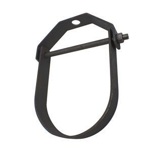
Fig B260 Adjustable Clevis Hanger
Manufacturers:
The figure B260 carbon steel adjustable clevis hanger is designed to support stationary lines from above, allowing for approximately 1” to 1-1/2” of vertical adjustment after the pipe is in place. The lower load nut (not furnished), adjusts the pipe line to the proper elevation while the top load nut (not furnished), prevents loosening due to vibration, must be installed, and tightened securely, to assure proper hanger performance.
Products
Installation Drawings


Product Details
| MATERIAL | Carbon Steel |
| MAX TEMP | 650F (343C) |
| COMPLIANCE | Federal Specification A-A-1192A (Type 1), ANSI/MSS SP-58 (Type 1). UL and FM approved for Sizes 3/4” through 8” only. |
| NOTE | Punched forming holes may be present on certain sizes of this clevis hanger. These holes are solely for the purpose of manufacturing, and do not effect the structural integrity or load carrying capacities of these hangers. For insulated line options without shields, see Clevis Hanger w/Insulation Saddle System and Adjustable Clevis for Insulated Lines. For insulated line options with shields, see Insulation Protection Shield. For ductile iron pipe sizes, see Adjustable Clevis, sizes 3" through 24". Caution: When an oversize clevis is used, a pipe spacer or multispacer should be placed over clevis bolt to ensure that the lower U-strap will not move in on the bolt. |
Dimensions & Loads

| PIPE SIZE | MAX LOAD | A | B | C | ROD TAKE OUT E | WEIGHT EACH |
| 1/2 | 730 | 3/8 | 2 3/4 | 3 1/8 | 1 7/8 | 0.27 |
| 3/4 | 730 | 3/8 | 2 1/8 | 2 3/4 | 1 1/2 | 0.29 |
| 1 | 730 | 3/8 | 3 | 3 3/4 | 2 1/4 | 0.33 |
| 1 1/4 | 730 | 3/8 | 3 1/8 | 4 | 2 1/4 | 0.36 |
| 1 1/2 | 730 | 3/8 | 3 1/4 | 4 1/4 | 2 3/8 | 0.42 |
| 2 | 730 | 3/8 | 3 3/8 | 4 5/8 | 3 1/8 | 0.52 |
| 2 1/2 | 1350 | 1/2 | 4 1/8 | 5 5/8 | 3 1/8 | 0.61 |
| 3 | 1350 | 1/2 | 5 | 6 7/8 | 4 1/8 | 0.90 |
| 3 1/2 | 1350 | 1/2 | 4 1/2 | 6 5/8 | 3 5/8 | 0.99 |
| 4 | 1430 | 5/8 | 5 3/8 | 7 3/4 | 4 3/8 | 1.40 |
| 5 | 1430 | 5/8 | 6 | 8 7/8 | 5 | 2.10 |
| 6 | 1940 | 3/4 | 7 | 10 1/2 | 5 7/8 | 3.00 |
| 7 | 2000 | 3/4 | 7 5/8 | 11 3/4 | 6 1/2 | 5.42 |
| 8 | 2000 | 3/4 | 8 1/2 | 12 3/4 | 6 3/4 | 4.50 |
| 10 | 3600 | 7/8 | 10 | 15 3/8 | 8 1/4 | 9.10 |
| 12 | 3800 | 7/8 | 11 1/8 | 17 1/2 | 9 1/4 | 11.75 |
| 14 | 4200 | 1 | 12 1/2 | 19 1/2 | 10 5/8 | 14.25 |
| 16 | 4800 | 1 | 15 | 23 | 13 1/8 | 20.75 |
| 18 | 4800 | 1 1/4 | 15 3/4 | 24 3/4 | 13 3/4 | 23.00 |
| 20 | 4800 | 1 1/4 | 17 3/8 | 27 3/8 | 15 1/4 | 41.50 |
| 24 | 4800 | 1 1/4 | 19 5/8 | 31 5/8 | 17 1/2 | 50.00 |
| 30 | 6000 | 1 1/4 | 24 3/4 | 40 3/4 | 21 3/4 | 68.08 |
| 36 | 9500 | 1 1/2 | 32 7/8 | 50 7/8 | 30 | 68.68 |
- All dimensions are in inches.