
Fig B86 C-Clamp With Lock Nut
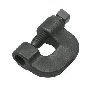
Fig B86 C-Clamp With Lock Nut
Manufacturers:
The figure B86 malleable iron c-clamp with set screw and locknut is designed to attach mechanically to the bottom flange of a steel beam and may require a Fig. B89 retaining clip to prevent loosening due to vibration after installation.
Products
Dimensions & Loads

| ROD SIZE A |
MAX LOAD |
PIPE SIZES | C | D | E | F | WEIGHT EACH |
| 3/8 | 400 | 1/2 to 2 | 1 3/4 | 1 3/4 | 5/8 | 3/4 | 0.33 |
| 1/2 | 400 | 2 1/2 to 3 1/2 | 1 3/4 | 1 3/4 | 5/8 | 3/4 | 0.39 |
| 5/8 | 440 | 4 to 5 | 2 | 2 | 3/4 | 3/4 | 0.46 |
| 3/4 | 500 | 6 | 2 | 2 | 3/4 | 3/4 | 0.52 |
- All dimensions are in inches.
Installation Drawings

Product Details
| MATERIAL | Malleable Iron with Hardened Steel Cup Point Set Screw |
| COMPLIANCE | Federal Specification A-A-1192A (Type 23) ANSI/MSS SP-58 (Type 23) |
| NOTE | Install in accordance with ANSI / MSS SP-58 set screw torque values. Malleable body assures uniform quality and strength and full thread engagement. Hardened steel cup point set screw for securing to beam flange. Ribbed design of clamp provides added strength. |