
A105 Raised Face Threaded Flange
A105 Raised Face Threaded Flange
Item #: A105 Raised Face Threaded Flange
Manufacturers:
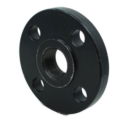
The A105 Raised Face Threaded Neck Flange is an essential fitting used to create a secure connection in piping systems. Manufactured in accordance with ASME B16.5 specifications, this flange is made from carbon steel, ensuring its capability in withstanding high temperatures and pressures.The raised face design increases the contact area for gaskets and its threaded neck allows for easy installation and removal, making it a convenient option for systems requiring frequent maintenance or adjustments.
Products
Chemical Properties
| Element | Carbon | Manganese | Phosphorus | Sulfur | Silicon | Copper | Nickel | Chromium | Molybdenum | Vanadium |
| Composition, % | 0.35 max | 0.60-1.05 | 0.035 max | 0.040 max | 0.10-0.35 | 0.40 max (1) | 0.40 max (1) | 0.30 max (1-2) | 0.12 max (1-2) | 0.08 max |
- 1. The sum of copper, nickel, chromium, molybdenum and vanadium shall not exceed 1.00%
- 2. The sum of chromium and molybdenum shall not exceed 0.32%
- Note: For each reduction of 0.01% below the specified carbon maximum (0.35%), an increase of 0.006% manganese above the specified maximum (1.05%) will be permitted up to a maximum of 1.35%.
Dimensional Specifications


Class #150 Dimensions |
Length Through Hub | Drilling | Length of Bolts | |||||||||
| Pipe Size | Outside Diameter of Flange | Thickness of Flange (Min.) | Diameter of Hub | Threaded Length Through Hub Neck | Thread Length (Min.) | Diameter of Bolt Circle | Diameter of Bolt Holes | Number of Bolt Holes | Diameter of Bolts | Stud Bolts Raised Face 0.06 in. | Stud Bolts Ring Joint | Machine Bolts Raised Face 0.06 in. |
| O.D. | C | W | Y2 | T | M | P | P | P | ||||
| 1/2 | 3.50 | 0.38 | 1.19 | 0.56 | 0.62 | 2.38 | 5/8 | 4.00 | 1/2 | 2.25 | 2.00 | |
| 3/4 | 3.88 | 0.44 | 1.50 | 0.56 | 0.62 | 2.75 | 5/8 | 4.00 | 1/2 | 2.50 | 2.00 | |
| 1 | 4.25 | 0.50 | 1.94 | 0.62 | 0.69 | 3.12 | 5/8 | 4.00 | 1/2 | 2.50 | 3.00 | 2.25 |
| 1 1/4 | 4.62 | 0.56 | 2.31 | 0.75 | 0.81 | 3.50 | 5/8 | 4.00 | 1/2 | 2.75 | 3.25 | 2.25 |
| 1 1/2 | 5.00 | 0.62 | 2.56 | 0.81 | 0.88 | 3.88 | 5/8 | 4.00 | 1/2 | 2.75 | 3.25 | 2.50 |
| 2 | 6.00 | 0.69 | 3.06 | 0.94 | 1.00 | 4.75 | 3/4 | 4.00 | 5/8 | 3.25 | 3.75 | 2.75 |
| 2 1/2 | 7.00 | 0.81 | 3.56 | 1.06 | 1.12 | 5.50 | 3/4 | 4.00 | 5/8 | 3.50 | 4.00 | 3.00 |
| 3 | 7.50 | 0.88 | 4.25 | 1.12 | 1.19 | 6.00 | 3/4 | 4.00 | 5/8 | 3.50 | 4.00 | 3.00 |
| 3 1/2 | 8.50 | 0.88 | 4.81 | 1.19 | 1.25 | 7.00 | 3/4 | 8.00 | 5/8 | 3.50 | 4.00 | 3.00 |
| 4 | 9.00 | 0.88 | 5.31 | 1.25 | 1.31 | 7.50 | 3/4 | 8.00 | 5/8 | 3.50 | 4.00 | 3.00 |
| 5 | 10.00 | 0.88 | 6.44 | 1.38 | 1.44 | 8.50 | 7/8 | 8.00 | 3/4 | 3.75 | 4.25 | 3.25 |
| 6 | 11.00 | 0.94 | 7.56 | 1.50 | 1.56 | 9.50 | 7/8 | 8.00 | 3/4 | 4.00 | 4.50 | 3.25 |
| 8 | 13.50 | 1.06 | 9.69 | 1.69 | 1.75 | 11.75 | 7/8 | 8.00 | 3/4 | 4.25 | 4.75 | 3.50 |
| 10 | 16.00 | 1.12 | 12.00 | 1.88 | 1.94 | 14.25 | 1 | 12.00 | 7/8 | 4.50 | 5.00 | 4.00 |
| 12 | 19.00 | 1.19 | 14.38 | 2.12 | 2.19 | 17.00 | 1 | 12.00 | 7/8 | 4.75 | 5.25 | 4.00 |
| 14 | 21.00 | 1.31 | 15.75 | 2.19 | 2.25 | 18.75 | 1 1/8 | 12.00 | 1 | 5.25 | 5.75 | 4.50 |
| 16 | 23.50 | 1.38 | 18.00 | 2.44 | 2.50 | 21.25 | 1 1/8 | 16.00 | 1 | 5.25 | 5.75 | 4.50 |
| 18 | 25.00 | 1.50 | 19.80 | 2.62 | 2.69 | 22.75 | 1 1/4 | 16.00 | 1 1/8 | 5.75 | 6.25 | 5.00 |
| 20 | 27.50 | 1.62 | 22.00 | 2.81 | 2.88 | 25.00 | 1 1/4 | 20.00 | 1 1/8 | 6.25 | 6.75 | 5.50 |
| 24 | 32.00 | 1.81 | 26.12 | 3.19 | 3.25 | 29.50 | 1 3/8 | 20.00 | 1 1/8 | 6.75 | 7.25 | 6.00 |
Class #300 Dimensions |
Drilling | Length of Bolts | Length Through Hub | Bore | |||||||||
| Pipe Size | Outside Diameter of Flange | Thickness of Flange (Min.) | Diameter of Bolt Circle | Diameter of Bolt Holes | Number of Bolt Holes | Diameter of Bolts | Stud Bolts Raised Face 0.06 in. | Stud Bolts Ring Joint | Machine Bolts Raised Face 0.06 in. | Diameter of Hub | Threaded Length Through Hub Neck | Slip-on Bore (Min.) | Thread Length (Min.) |
| O.D. | C | M | P | P | P | W | Y2 | B2 | T | ||||
| 1/2 | 3.75 | 0.5 | 2.62 | 5/8 | 4 | 1/2 | 2.50 | 3.00 | 2.25 | 1.5 | 0.81 | 0.88 | 0.62 |
| 3/4 | 4.62 | 0.56 | 3.25 | 3/4 | 4 | 5/8 | 3.00 | 3.50 | 2.50 | 1.88 | 0.94 | 1.09 | 0.62 |
| 1 | 4.88 | 0.62 | 3.5 | 3/4 | 4 | 5/8 | 3.00 | 3.50 | 2.50 | 2.12 | 1.00 | 1.36 | 0.69 |
| 1 1/4 | 5.25 | 0.69 | 3.88 | 3/4 | 4 | 5/8 | 3.25 | 3.75 | 2.75 | 2.5 | 1.00 | 1.70 | 0.81 |
| 1 1/2 | 6.12 | 0.75 | 4.50 | 7/8 | 4 | 3/4 | 3.50 | 4.00 | 3.00 | 2.75 | 1.13 | 1.95 | 0.88 |
| 2 | 6.50 | 0.81 | 5.00 | 3/4 | 8 | 5/8 | 3.50 | 4.00 | 3.00 | 3.31 | 1.25 | 2.44 | 1.12 |
| 2 1/2 | 7.50 | 0.94 | 5.88 | 7/8 | 8 | 3/4 | 4.00 | 4.50 | 3.25 | 3.94 | 1.44 | 2.94 | 1.25 |
| 3 | 8.25 | 1.06 | 6.62 | 7/8 | 8 | 3/4 | 4.25 | 4.75 | 3.50 | 4.62 | 1.63 | 3.57 | 1.25 |
| 3 1/2 | 9.00 | 1.12 | 7.25 | 7/8 | 8 | 3/4 | 4.25 | 5.00 | 3.75 | 5.25 | 1.69 | 4.07 | 1.44 |
| 4 | 10.00 | 1.19 | 7.88 | 7/8 | 8 | 3/4 | 4.50 | 5.00 | 3.75 | 5.75 | 1.82 | 4.57 | 1.44 |
| 5 | 11.00 | 1.31 | 9.25 | 7/8 | 8 | 3/4 | 4.75 | 5.25 | 4.25 | 7.00 | 1.94 | 5.66 | 1.69 |
| 6 | 12.50 | 1.38 | 10.62 | 7/8 | 12 | 3/4 | 4.75 | 5.50 | 4.25 | 8.12 | 2.00 | 6.72 | 1.81 |
| 8 | 15.00 | 1.56 | 13.00 | 1 | 12 | 7/8 | 5.50 | 6.00 | 4.75 | 10.25 | 2.38 | 8.72 | 2.00 |
| 10 | 17.50 | 1.81 | 15.25 | 1 1/8 | 16 | 1 | 6.25 | 6.75 | 5.50 | 12.62 | 2.56 | 10.88 | 2.19 |
| 12 | 20.50 | 1.94 | 17.75 | 1 1/4 | 16 | 1 1/8 | 6.75 | 7.25 | 5.75 | 14.75 | 2.82 | 12.88 | 2.38 |
| 14 | 23.00 | 2.06 | 20.25 | 1 1/4 | 20 | 1 1/8 | 7.00 | 7.50 | 6.25 | 16.75 | 2.94 | 14.14 | 2.50 |
| 16 | 25.50 | 2.19 | 22.50 | 1 3/8 | 20 | 1 1/4 | 7.50 | 8.00 | 6.50 | 19.00 | 3.19 | 16.16 | 2.69 |
| 18 | 28.00 | 2.31 | 24.75 | 1 3/8 | 24 | 1 1/4 | 7.75 | 8.25 | 6.75 | 21.00 | 3.44 | 18.18 | 2.75 |
| 20 | 30.50 | 2.44 | 27.00 | 1 3/8 | 24 | 1 1/4 | 8.00 | 8.75 | 7.25 | 23.12 | 3.69 | 20.20 | 2.88 |
| 24 | 36.00 | 2.69 | 32.00 | 1 5/8 | 24 | 1 1/2 | 9.00 | 10.00 | 8.00 | 27.62 | 4.13 | 24.25 | 3.25 |
Class #600 Dimensions |
Drilling | Length of Bolts | Length Through Hub | Bore | ||||||||||||||||||||||||||
| Pipe Size | Outside Diameter of Flange | Thickness of Flange (Min.) | Diameter of Bolt Circle | Diameter of Bolt Holes | Number of Bolt Holes | Diameter of Bolts | Raised Face 0.25 in. | Tongue & Groove | Ring Joint | Diameter of Hub | Threaded Length Through Hub Neck | Slip-on Bore (Min.) | Thread Length (Min.) | Min. Counter Bore Threaded Flange | ||||||||||||||||
| O.D. | C | M | P | P | P | W | Y2 | B2 | T | Z | ||||||||||||||||||||
| 1/2 | 3.75 | 0.56 | 2.62 | 5/8 | 4 | 1/2 | 3.00 | 2.75 | 3.00 | 1.50 | 0.88 | 0.88 | 0.62 | 0.93 | ||||||||||||||||
| 3/4 | 4.62 | 0.62 | 3.25 | 3/4 | 4 | 5/8 | 3.50 | 3.25 | 3.50 | 1.88 | 1 | 1.09 | 0.62 | 1.14 | ||||||||||||||||
| 1 | 4.88 | 0.69 | 3.50 | 3/4 | 4 | 5/8 | 3.50 | 3.25 | 3.50 | 2.12 | 1.06 | 1.36 | 0.69 | 1.41 | ||||||||||||||||
| 1 1/4 | 5.25 | 0.81 | 3.88 | 3/4 | 4 | 5/8 | 3.75 | 3.50 | 3.75 | 2.5 | 1.12 | 1.70 | 0.81 | 1.75 | ||||||||||||||||
| 1 1/2 | 6.12 | 0.88 | 4.50 | 7/8 | 4 | 3/4 | 4.25 | 4.00 | 4.25 | 2.75 | 1.25 | 1.95 | 0.88 | 1.99 | ||||||||||||||||
| 2 | 6.50 | 1.00 | 5.00 | 3/4 | 8 | 5/8 | 4.25 | 4.00 | 4.25 | 3.31 | 1.44 | 2.44 | 1.12 | 2.50 | ||||||||||||||||
| 2 1/2 | 7.50 | 1.12 | 5.88 | 7/8 | 8 | 3/4 | 4.75 | 4.50 | 4.75 | 3.94 | 1.62 | 2.94 | 1.25 | 3.00 | ||||||||||||||||
| 3 | 8.25 | 1.25 | 6.62 | 7/8 | 8 | 3/4 | 5.00 | 4.75 | 5.00 | 4.62 | 1.81 | 3.57 | 1.38 | 3.63 | ||||||||||||||||
| 3 1/2 | 9.00 | 1.38 | 7.25 | 1 | 8 | 7/8 | 5.50 | 5.25 | 5.50 | 5.25 | 1.94 | 4.07 | 1.56 | 4.13 | ||||||||||||||||
| 4 | 10.75 | 1.50 | 8.50 | 1 | 8 | 7/8 | 5.75 | 5.50 | 5.75 | 6.00 | 2.12 | 4.57 | 1.62 | 4.63 | ||||||||||||||||
| 5 | 13.00 | 1.75 | 10.50<
Mechanical Properties
Governing Standards
Loading product details...
| |||||||||||||||||||||||||||