
Fig G212 Medium Pipe Clamp, Galvanized
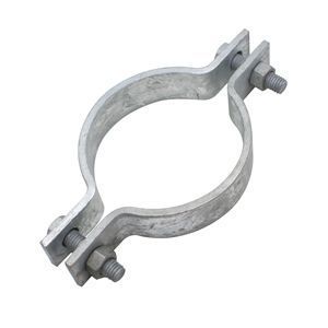
Fig G212 Medium Pipe Clamp, Galvanized
Manufacturers:
The figure G212 hot dipped galvanized medium pipe clamp is designed to suspend cold or hot pipe lines where little or no insulation is required. The Fig. G212 medium pipe clamp is usually used with a Fig. G290 weldless eyenut or a Fig. G278 welded eye rod.
Products
Product Details
| MATERIAL | Carbon Steel |
| MAX TEMP | 750F (399C) |
| COMPLIANCE | Federal Specification A-A-1192A (Type 4), ANSI/MSS SP-58 (Type 4) |
| NOTE | The “C” gap dimension ensures adequate clearance at the top attachment point for a weldless eye nut or other appropriate rod attachment. This gap may or may not be present on the bottom portion of the clamp. If different loads or dimensions are required, refer to non-standard two bolt pipe clamp. |
Dimensions & Loads


| PIPE SIZE | MAXIMUM LOAD | C | D | E | F | WEIGHT EA | |
| 650F (343 C) | 750F (399C) | ||||||
| 1/2 | 500 | 445 | 3/8 | 1 1/8 | 1 5/8 | 3/8 | 0.31 |
| 3/4 | 500 | 445 | 3/8 | 1 1/4 | 1 3/4 | 3/8 | 0.35 |
| 1 | 500 | 445 | 3/8 | 1 3/8 | 1 7/8 | 3/8 | 0.39 |
| 1 1/4 | 500 | 445 | 3/8 | 1 5/8 | 2 1/8 | 3/8 | 0.40 |
| 1 1/2 | 800 | 715 | 3/8 | 1 3/4 | 2 1/4 | 3/8 | 0.45 |
| 2 | 1040 | 930 | 1/2 | 2 1/8 | 2 3/4 | 1/2 | 1.23 |
| 2 1/2 | 1040 | 930 | 5/8 | 2 5/8 | 3 1/8 | 1/2 | 1.33 |
| 3 | 1040 | 930 | 5/8 | 3 | 3 5/8 | 1/2 | 1.53 |
| 4 | 1040 | 930 | 3/4 | 3 5/8 | 4 3/8 | 1/2 | 2.20 |
| 5 | 1040 | 930 | 3/4 | 4 1/4 | 5 | 1/2 | 2.39 |
| 6 | 1615 | 1440 | 7/8 | 5 1/4 | 6 1/4 | 3/4 | 5.87 |
| 8 | 1615 | 1440 | 1 | 6 3/8 | 7 3/8 | 3/4 | 6.95 |
| 10 | 2490 | 2220 | 1 | 7 5/8 | 8 3/4 | 7/8 | 14.39 |
| 12 | 2490 | 2220 | 1 | 8 3/4 | 10 1/4 | 7/8 | 16.73 |
| 14 | 2490 | 2220 | 1 1/8 | 9 1/4 | 10 5/8 | 7/8 | 21.26 |
| 16 | 2490 | 2220 | 1 1/8 | 10 1/4 | 11 5/8 | 7/8 | 23.39 |
| 18 | 3060 | 2730 | 1 1/4 | 11 5/8 | 13 | 1 | 32.96 |
| 20 | 3060 | 2730 | 1 3/8 | 12 3/4 | 14 1/8 | 1 1/8 | 36.74 |
| 24 | 3060 | 2730 | 1 1/2 | 15 1/4 | 16 7/8 | 1 1/4 | 52.96 |
| 30 | 3500 | 3360 | 2 | 18 1/2 | 20 3/4 | 1 1/2 | 103.50 |
- All dimensions are in inches.
Installation Drawings


